

Shape measurement of specular reflective surface
A technique for specular reflection and measurement of flat surfaces, applied in the field of the shape of objects
Inactive Publication Date: 2010-08-25
CORNING INC
View PDF7 Cites 22 Cited by
- Summary
- Abstract
- Description
- Claims
- Application Information
AI Technical Summary
Problems solved by technology
It is not possible to uniquely determine the shape of a specular surface without knowing the position of the reflection point on the specular surface
Method used
View moreImage
Smart ImageViewing Examples

Examples
example 1
example 2
Login to View More PUM
 Abstract
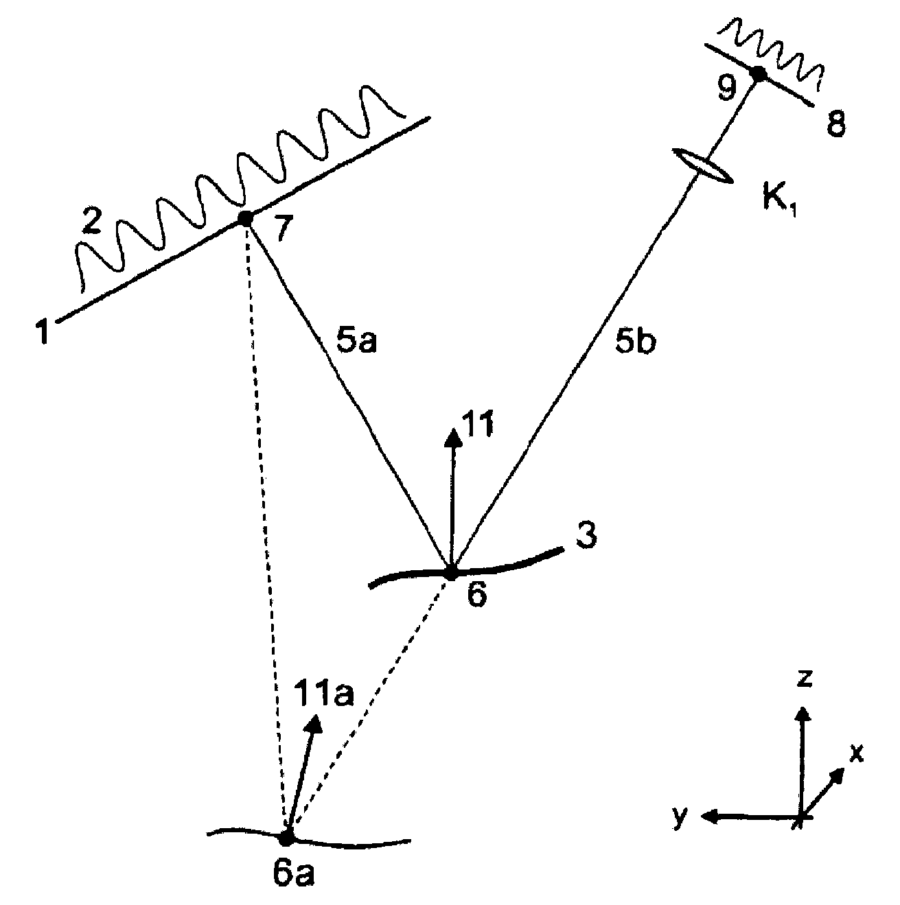
A method of measuring a shape of a specular reflective surface is provided. A pattern displayed on a surface of a target positioned at a target plane is produced from a specular reflective surface positioned at a measurement plane. An image of the reflection is recorded at an imaging plane. Positions of a plurality of points on the specular reflective surface relative to the imaging plane are determined. A first relation between feature positions on the image of the reflection and feature positions on the pattern is determined. The shape of the specular reflective surface is determined from asecond relation involving a surface profile of the specular reflective surface and the first relation using the positions of the plurality of points as an initial condition.
Description
Shape measurement of specularly reflective surfaces priority This application claims priority to US Patent Application 12 / 391,585, filed February 24, 2009, entitled "Shape Measurement of Specular Reflective Surface." technical field The present invention generally relates to optical methods and apparatus for measuring the shape of objects. More particularly, the present invention relates to methods and apparatus for measuring the shape of objects having specularly reflective surfaces. Background technique The fusion drawing process is used to create sheets of material from molten material such as molten glass (see US Patent 3,338,696 and US Patent 3,682,609). Generally, the melt drawing process includes: delivering molten material into a trough; and allowing the molten material to spill down the sides of the trough in a controlled manner. The separate streams of material flowing down the sides of the trough are combined at the bottom of the trough into a single stream...
Claims
Login to View More Application Information
Patent Timeline
 IPC IPC(8): G01B11/24C03B23/02
CPCH04N7/18C03B17/064G01B11/2513G01B11/25G01B11/30G01N21/86
InventorS·波塔彭科
OwnerCORNING INC