

Engine piston position and phase position full operation condition measurement system and method
A technology of piston position and measurement system, applied in the direction of internal combustion engine testing, etc., can solve the problem of inability to measure the position of the piston of the engine, small or even zero, etc.
Inactive Publication Date: 2010-08-25
JILIN UNIV
View PDF0 Cites 25 Cited by
- Summary
- Abstract
- Description
- Claims
- Application Information
AI Technical Summary
Problems solved by technology
Technical problem: Traditional engines often use electromagnetic induction sensors for signals such as crankshaft speed. The structure of this sensor generally contains a permanent magnet and an induction coil. The change of the valley makes the magnetic field change, and an AC voltage is induced in the coil, and its frequency and amplitude change with the engine speed. When the engine is at low speed, the signal amplitude will be small or even zero, so it is impossible to measure the engine at low Piston position and cylinder phase at speed
Method used
View moreImage
Smart ImageViewing Examples


Examples
Embodiment Construction
Login to View More PUM
 Abstract
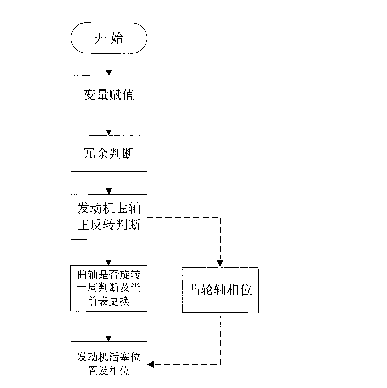
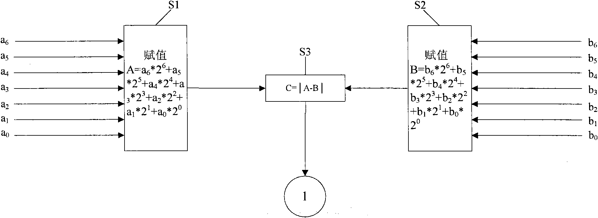
The invention relates to engine piston position and phase position full operation condition measurement system and method which can accurately measure the stop position of an engine piston and the phase position of each cylinder and can judge the forward and reverse rotation of an engine crankshaft. In the invention, a photoelectric element is adopted as a sensor and can generate accurate signals when at a low speed; 128 different notches are evenly distributed on a designed crankshaft signal target disc; and 128 sets of different signals are generated when the signal target disc rotates in a circle with the crankshaft to mark the absolute position of the piston and judge the forward and reverse rotation of the engine. The four effect areas of a camshaft signal target disc also can mark the phase position of the engine. The measurement system and method designed by the invention can meet real-time piston position and engine phase monitoring of an instant inversion and direct start-stop system of a direct inject gasoline engine in aspects of function and accuracy and can complete measurement of crankshaft rotation speed and camshaft phase position.
Description
technical field The invention relates to an engine piston position and phase full working condition measurement system and a measuring method, which belong to the measurement of the engine piston position and phase in the full working condition range and the judgment of the forward and reverse rotation of the crankshaft. Background technique Most of the automobile engines in our country use electromagnetic speed sensors and camshaft phase sensors, so it is impossible to measure the position of the engine piston and the phase of each cylinder when it stops. At present, the measurement system that can accurately measure the stop position of the engine piston and the phase of each cylinder and can judge the forward and reverse rotation of the engine crankshaft is still blank. In order to realize the closed-loop control of the piston position in order to meet the needs of the instantaneous reverse direct start-stop system of the direct injection gasoline engine, the stop positio...
Claims
Login to View More Application Information
Patent Timeline
 IPC IPC(8): G01M15/06G01M15/04
Inventor于秀敏许楠何玲宫长明李国良梁金广孙平董伟齐万强张允
OwnerJILIN UNIV