

Mechanical clamping type automatic feeding and discharging device
A technology of automatic discharging device and automatic feeding, which is applied in measurement devices, analytical materials, testing of machine/structural components, etc. The overall structure is ingenious and reasonable, and the effect of improving production efficiency
Inactive Publication Date: 2010-08-25
无锡昌华机电制造有限公司
View PDF4 Cites 16 Cited by
- Summary
- Abstract
- Description
- Claims
- Application Information
AI Technical Summary
Problems solved by technology
This method of operation is not only labor-intensive and low-efficiency, but also has many disadvantages such as irregular operations and potential safety hazards.
Method used
View moreImage
Smart ImageViewing Examples

Examples
Embodiment Construction
Login to View More PUM
 Abstract
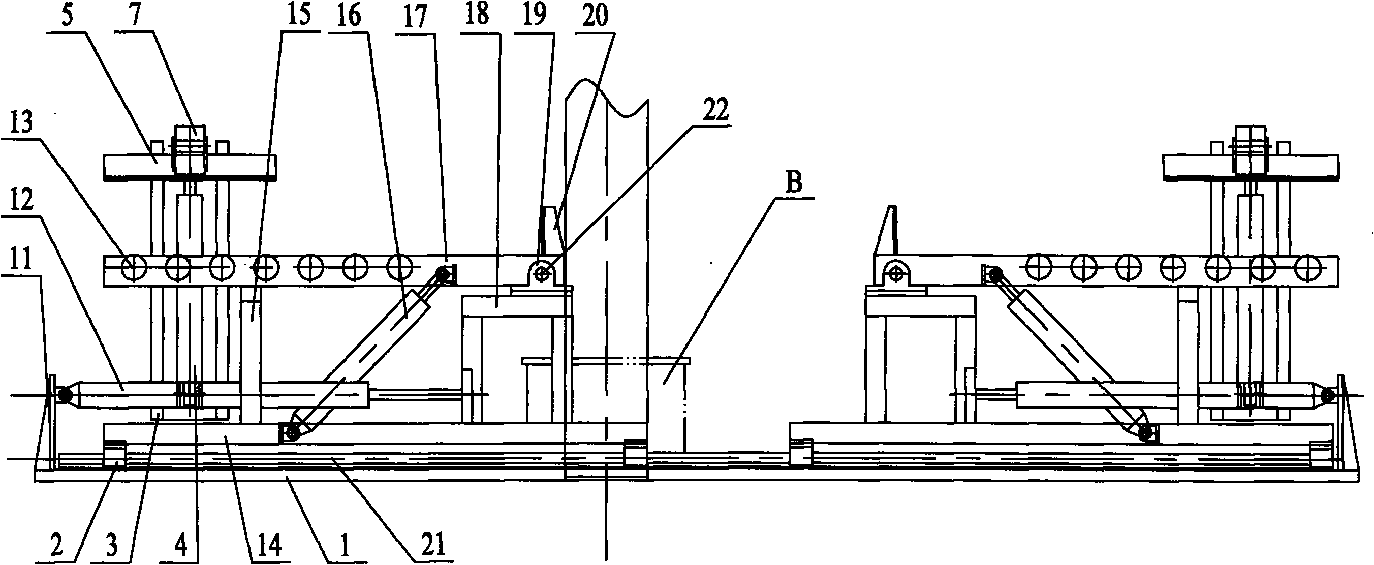
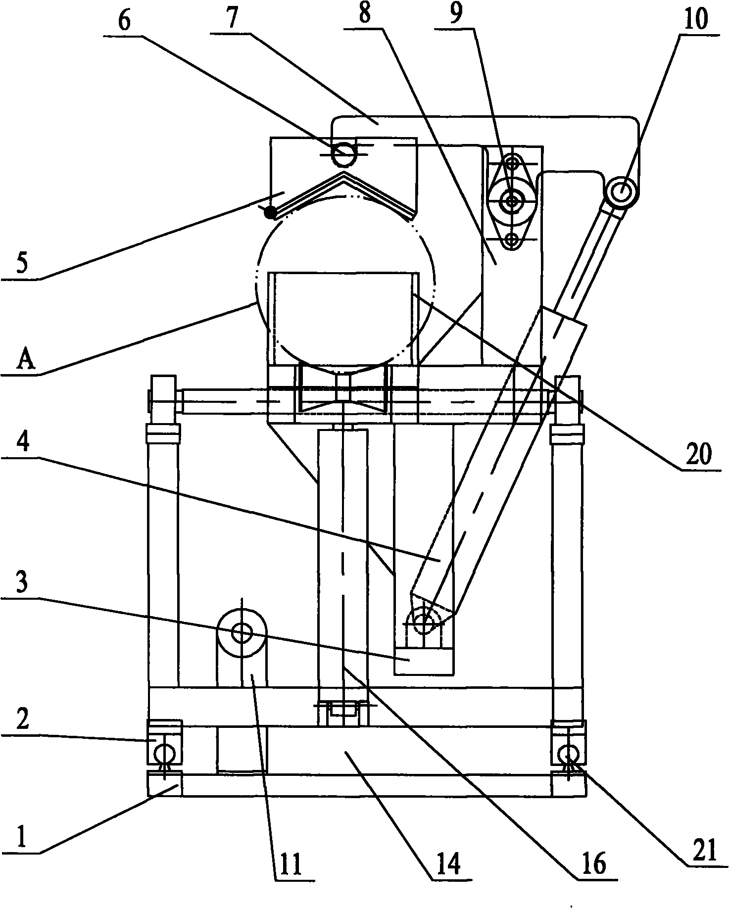
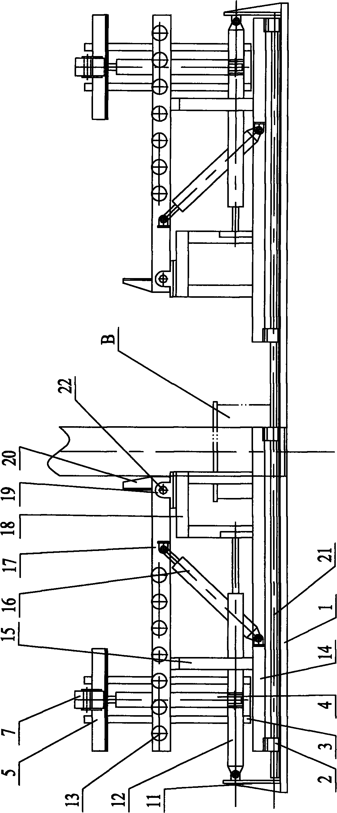
The invention relates to a mechanical clamping type automatic feeding and discharging device, which is applied on a production line of hydraulic tests in a water jacket method for gas cylinders. The device comprises a linear guide rail mechanism, an automatic feeding device and an automatic discharging device, wherein the automatic feeding device and the automatic discharging device are supported by the linear guide rail mechanism and can freely slide on the linear guide rail. The device is characterized in that the automatic feeding device and the automatic discharging device are of identical structures and are symmetrically arranged on the two ends of the linear guide rail; the automatic feeding device and the automatic discharging device are respectively driven by a power mechanism to slide in a reciprocating way along the linear guide rail; and the automatic feeding device and the automatic discharging device respectively comprise a base, an overturning frame and an overturning cylinder; the overturning cylinder are used for driving the overturning frames to overturn; the overturning frames comprise a roller frame, a roller and a clamping mechanism; the rollers are used for supporting an air cylinder to be tested; and the clamping mechanisms are used for fixing the air cylinder to be tested. The invention has the advantages of delicate and reasonable structure, convenient operation and high degree of automation, and can greatly improve the production efficiency, effectively reduce the labor intensity and ensure the personal safety of the operating personnel.
Description
A mechanical clamping type automatic feeding and discharging device technical field The invention relates to a transportation device for transferring gas cylinders to be tested on a hydraulic test production line of a gas cylinder external measurement method, in particular to a mechanical clamping type automatic feeding and discharging device. Background technique When carrying out the hydrostatic test of the gas cylinder external test method, the gas cylinder to be tested needs to go through three steps: the cylinder is in place, the test is completed, and the gas cylinder is out of position. At present, the above three steps all rely on manual movement of the gas cylinder. This mode of operation is not only labor-intensive and low-efficiency, but also irregular in operation and has many disadvantages such as potential safety hazards. Contents of the invention The purpose of the present invention is to overcome the deficiencies in the prior art and provide a mechanical...
Claims
Login to View More Application Information
Patent Timeline
 IPC IPC(8): G01N3/02G01M19/00G01M99/00
Inventor丁大为贾品华
Owner无锡昌华机电制造有限公司