System and method for detecting high voltage transmission line faults

A high-voltage transmission line and fault detection technology, applied in the direction of fault location, information technology support system, etc., can solve the problems of poor reliability of fault identification information, unresolved quickness, and high false alarm rate, so as to reduce industrial and agricultural production losses , Shorten troubleshooting time and reduce labor intensity

Inactive Publication Date: 2010-08-25
TIANJIN ZHILIAN HENGXIN ELECTRIC POWER EQUIP CO LTD
0 Cites 41 Cited by

AI-Extracted Technical Summary

Problems solved by technology

[0005] When a fault occurs, the line follower needs to check all the indicators, which cannot be resolved quickly. Sometimes, if the line is too long, it will take a lot of time to check all the indicators. Due to the complexity of the power grid, if the downstream users are large The start-up of electrical equipment will also cause misoperation of the indicator at the moment of start-up; and because it adopts the ironless method, the induction sensitivity is low; the main judgment basis of this equipment is the current change within the specified time length, and The internal time circuit will produce timing errors after working for a long time, resulting in fault analysis errors. After the actu...

Abstract

The invention relates to a system and a method for detecting high voltage transmission line faults. The system is provided with a fault analysis server and a detection device arranged on a three-phase high voltage transmission line, wherein the detection device consists of a first detection point device and two second detection point devices, the first detection point device is arranged on a B phase line, the second detection point devices are respectively arranged on an A phase line and a C phase line and transmit the detected data to the first detection point device, and the first detection point device transmits all of the detected data and the data transmitted by the second detection point devices to the fault analysis server. The method comprises the following steps of: arranging N detection points on one line, installing the detection device and synchronizing the time of each monitoring point; receiving monitored data of current, field intensity and temperature at any time transmitted by each detection device by the fault analysis server and carrying out statistic analysis. The invention can confirm the fault point of the high voltage transmission line in time, greatly improves the labor efficiency, and shortens the fault-checking time.

Application Domain

Technology Topic

Image

  • System and method for detecting high voltage transmission line faults
  • System and method for detecting high voltage transmission line faults
  • System and method for detecting high voltage transmission line faults

Examples

  • Experimental program(1)

Example Embodiment

[0032] In order to further understand the content, features and effects of the present invention, the following embodiments are given as examples, and the high-voltage transmission line fault detection system and detection method of the present invention are described in detail with the accompanying drawings as follows:
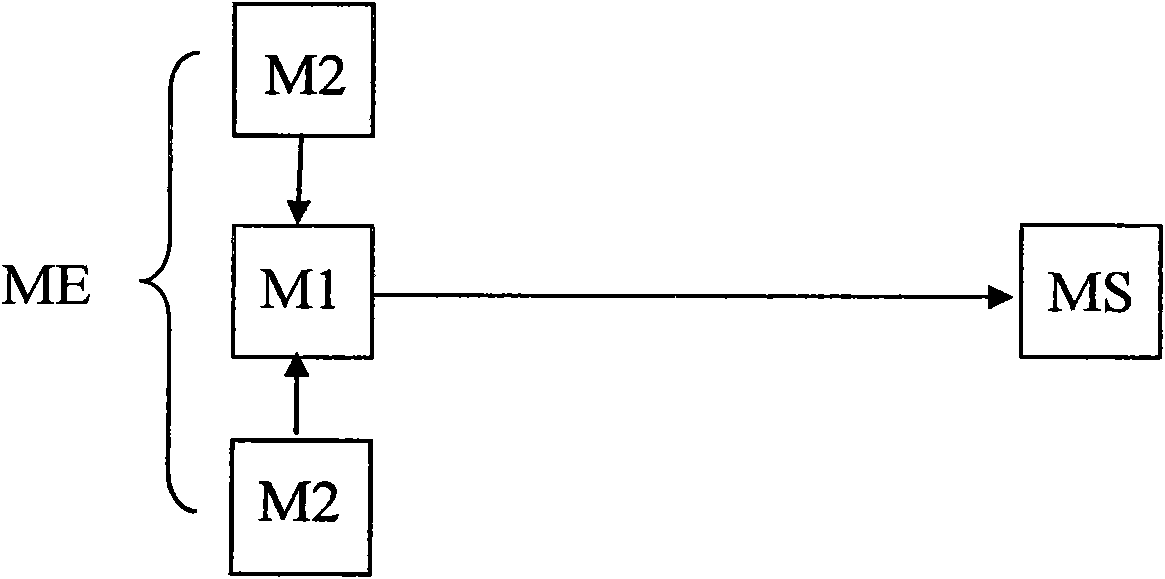
[0033] Such as figure 1 As shown, the high-voltage transmission line fault detection system of the present invention includes a fault analysis server MS and a detection device ME arranged at each detection point of the three-phase high-voltage transmission line for measuring the parameters of the detection point. The failure analysis server MS can be a computer. The detection device ME is composed of a first detection point device M1 and two second detection point devices M2. The one first detection point device M1 is arranged on the B-phase line of the three-phase high-voltage transmission line, The two second detection point devices M2 are arranged on the A-phase line and the C-phase line of the three-phase high-voltage transmission line, wherein the two second detection point devices M2 transmit the detected data to The first detection point device M1, the first detection point device M1 transmits all the detected data and the data transmitted by the two second detection point devices M2 to the fault analysis server MS.
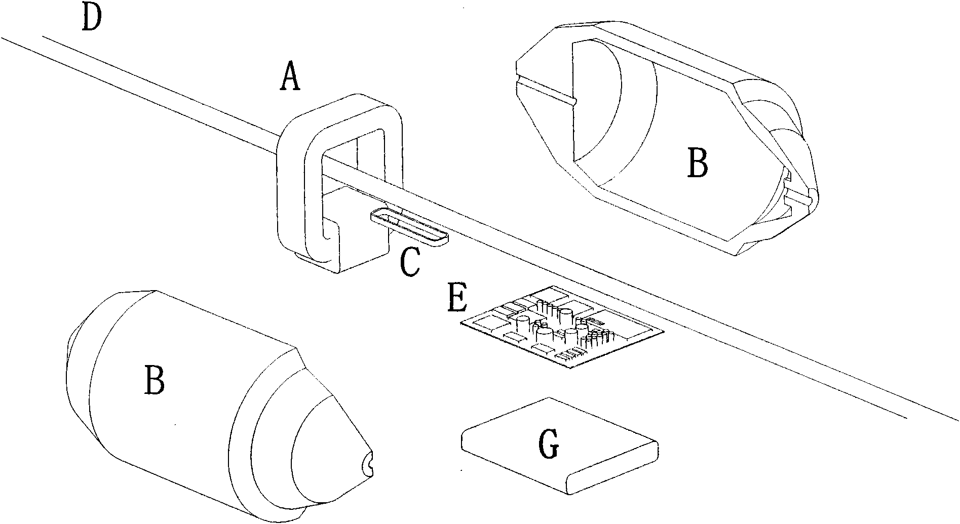
[0034] Such as figure 2 As shown, the first detection point device M1 includes a first current sensor A composed of a transformer with a high permeability iron core installed on the phase D of the high-voltage transmission line B, and is set on the phase B of the high-voltage transmission line. The first electric field intensity sensor C on the side D is the first signal processing unit E connected to the first current sensor A and the first electric field intensity sensor C respectively.
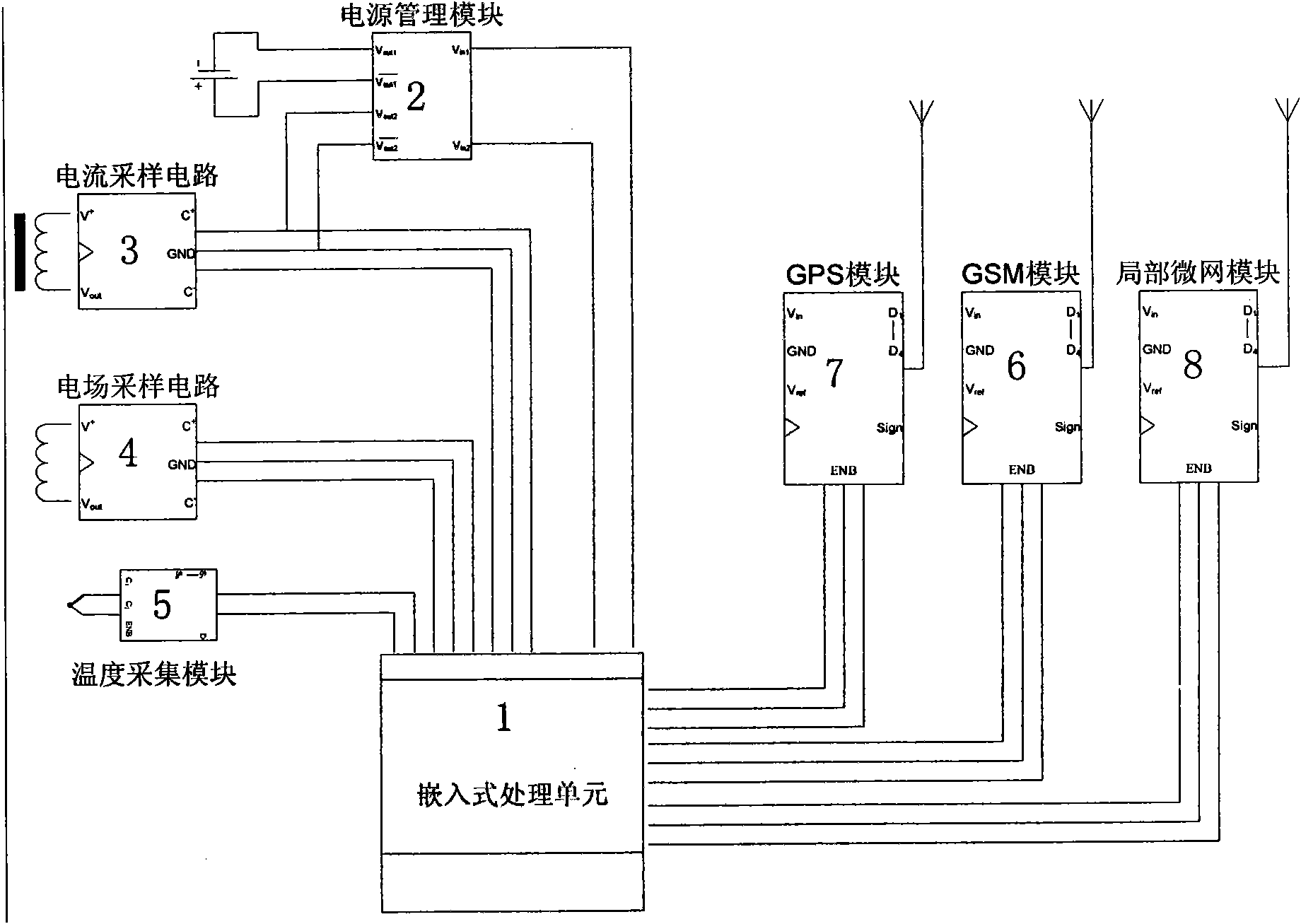
[0035] Such as image 3 As shown, the first signal processing unit E includes an embedded processing unit 1, a power management module 2 respectively connected to the embedded processing unit 1, a current sampling circuit 3 that receives a signal from the first current sensor A, and a first The electric field sampling circuit 4, the temperature sampling circuit 5, and the mobile communication network module 6 used to transmit data to the fault analysis server of the electric field strength sensor C signal select the GSM module, the global positioning system module used for timing and positioning, 7 select the GPS module and use the GPS module. In the local network module 8 communicating with the second detection point device M2.
[0036] Such as Figure 4 As shown, the second detection point device M2 includes a second current sensor A′ composed of a transformer with a high permeability iron core installed on the high-voltage transmission line A-phase/C-phase D′, and is installed on the high-voltage transmission line. The second electric field intensity sensor C′ on the side of the transmission line A phase/C phase D′, and a second signal processing unit E′ connected to the second current sensor A′ and the second electric field intensity sensor C′ respectively.
[0037] Such as Figure 5 As shown, the second signal processing unit E'includes a second embedded processing unit 9, a second power management module 10 respectively connected to the second embedded processing unit 9, and a signal receiving the second current sensor A' The second current sampling circuit 11, the second electric field sampling circuit 12 receiving the signal of the second electric field intensity sensor C', the second temperature sampling circuit 13, and the second local network module 14 for communicating with the first detection point device M1.
[0038] Such as figure 2 , Figure 4 As shown, the first detection point device M1 and the second detection point device M2 are correspondingly placed in the first housing B and the second housing B′.
[0039] The temperature sampling circuit described in the embodiment of the present invention is a built-in function of the central processing chip in the embedded processing unit; the embedded processing unit is such as Figure 7 As shown, the power management module is Figure 8 As shown, the electric field sampling circuit is Picture 9 As shown, the current sampling circuit is Picture 10 As shown, the GPS connection circuit is Picture 11 Shown.
[0040] The method of the present invention for high-voltage transmission line fault detection system is to set N detection points on one line, divide the line into N+1 sections, and install a GSM network and fault analysis server on each detection point The detection device ME through which the MS communicates and synchronizes the time of each monitoring point. The synchronization of the time of each monitoring point is a unified timing system formed by the GPS module in the detection device ME that can directly obtain the ephemeris time from the GPS satellite network , The monitoring data of each monitoring point has a time parameter. This time is the time when the monitoring event occurs. If the event is a fault event, this time is the time when the fault occurs.
[0041] At the same time, the standard physical parameters of voltage, current, and temperature of each monitoring point are set. The sampling time and sampling range of the physical parameters of each monitoring point are adjusted and set according to the specific use environment and conditions. The fault analysis server MS receives at any time the current, field strength and temperature data of the detected detection point from each detection device ME. When a short-circuit or open-circuit fault occurs in a section of the wire between the two detection points, the The current and field strength parameters monitored by the monitoring points before and after the fault point are inconsistent. The fault analysis server MS performs statistical analysis on the voltage, current, and temperature physical parameters of all monitoring points on the same line on the same time axis, and compares each before and after the fault time. The change trend of the physical parameters of the fault point is used to confirm between the two monitoring points where the fault point is located, so as to locate the line fault. The geographic location of the monitoring point is confirmed on the electronic map. And call the corresponding inspection personnel to check on the spot through the mobile communication network.
[0042] We use a single line to illustrate how the fault analysis server MS performs analysis: According to the current standard, if the line is short-circuited, the upper-level protection device will cut off the circuit within 0.4 seconds. According to the Nyquist criterion, we can get the following in conclusion:
[0043] T=0.4f=2.5HZ Our sampling frequency must be at least 5HZ to meet the sampling requirements of this system; because our sampling circuit has high technical indicators, we use a sampling accuracy of 100HZ, so that we can get a precise original The digital signal sequence after the signal waveform is discretely quantized;
[0044] From the above, we know that the sampled digital signal sequence is a function of relative time, assuming a line such as Image 6 As shown,
[0045] When a short-circuit fault occurs:
[0046] When a short-circuit fault occurs at point N, the current at point H will increase; point F will remain unchanged; the current at points L and P will decrease; at the same time, the field strength at points H, L, P, and F must decrease from the electric field sensor. , The current of the other unfaulted two-phase lines remains unchanged and the voltage must increase.
[0047] We store the sampled data FT1~FTn in a linked list structure, and then map the data to a 2-dimensional plane coordinate system. According to the slope formula k=(y2-y1)/(x2-x1), the adjacent data can be obtained in the 2-dimensional For the slope in the coordinate system, we can determine a theoretical slope of action according to the action current and trigger time parameters of the superior relay protection device (in actual applications, this parameter is tested before the system is put into operation) when the sampling result is the same as this value. When it exceeds, it will be regarded as alarm for this line;
[0048] The grounding of two lines is regarded as a phase-to-phase short circuit, and the method of phase-to-phase short-circuit analysis can be used. The criterion for distinguishing from a phase-to-phase short circuit is that the fault sections of the two lines are not necessarily the same;
[0049] When an open circuit fault occurs:
[0050] The half of the open circuit fault is relatively simple. Because the voltage and current after the open circuit point are all 0, it is only necessary to judge which monitoring point has a data slope of 0.
[0051] The high-voltage transmission line fault detection system and detection method of the present invention, by arranging multiple monitoring point devices on the same line, and synchronizing the time of each monitoring point through a unified timing system, confirms a distributed multi-point monitoring and wireless transmission transmission line Physical parameter method; the monitoring point equipment of the present invention can freely form a local micro-network.

PUM

no PUM

Description & Claims & Application Information

We can also present the details of the Description, Claims and Application information to help users get a comprehensive understanding of the technical details of the patent, such as background art, summary of invention, brief description of drawings, description of embodiments, and other original content. On the other hand, users can also determine the specific scope of protection of the technology through the list of claims; as well as understand the changes in the life cycle of the technology with the presentation of the patent timeline. Login to view more.

Similar technology patents

Classification and recommendation of technical efficacy words

  • Increase system capacity
  • High positioning accuracy

Interference Coordination Method and Base Station

ActiveUS20140106769A1Increase system capacityPower managementDistributed allocationCell basedPower margin
Owner:HUAWEI TECH CO LTD
Why Eureka
Try Eureka