Iris identification device by using camera array and multimodal biometrics identification method

A technology of iris recognition and camera, applied in character and pattern recognition, image communication, computer components, etc., can solve the problems of high price, slow speed, inconvenient use, etc., to expand the shooting range and depth of field, and increase the ease of use , apply a wide range of effects

Inactive Publication Date: 2010-08-25
INST OF AUTOMATION CHINESE ACAD OF SCI
View PDF5 Cites 45 Cited by
  • Summary
  • Abstract
  • Description
  • Claims
  • Application Information

AI Technical Summary

Problems solved by technology

[0003] Among biometric identification technologies, iris recognition technology has the advantages of high accuracy, strong uniqueness, and good anti-counterfeiting, which is very suitable for identity authentication of large-scale crowds. However, the disadvantage of iris recognition is that it is very difficult to obtain iris images. Inconvenient to use
[0004] Existing iris recognition patent products (such as Chinese patents CN1282048, CN1416779, CN1584917, CN1752990, CN1439998, etc.) all use one or two cameras for recognition, and the shooting range is very narrow, which cannot adapt to users of different heights
There are some systems that use a rotating device to automatically align the camera to the eye area of ​​the person, but this device can accommodate users of different heights, but the disadvantage is that it is slower
Some systems use high-resolution cameras, but such devices are expensive and have slow image transmission speeds, making them impractical
In short, the shooting range of a camera is very limited and cannot adapt to complex application scenarios. Only by using multiple cameras can the purpose of flexibility and convenience be achieved.
[0005] On the other hand, most of the existing iris devices can only work at a very short distance (about 0.5 meters), which is very inconvenient for users to use; while most of the iris cameras at long distances (above 1 meter) are expensive and not suitable for practical use

Method used


Image

  • Iris identification device by using camera array and multimodal biometrics identification method
  • Iris identification device by using camera array and multimodal biometrics identification method
  • Iris identification device by using camera array and multimodal biometrics identification method

Examples


Embodiment 1

[0068] Embodiment 1: Applied to long-distance iris recognition

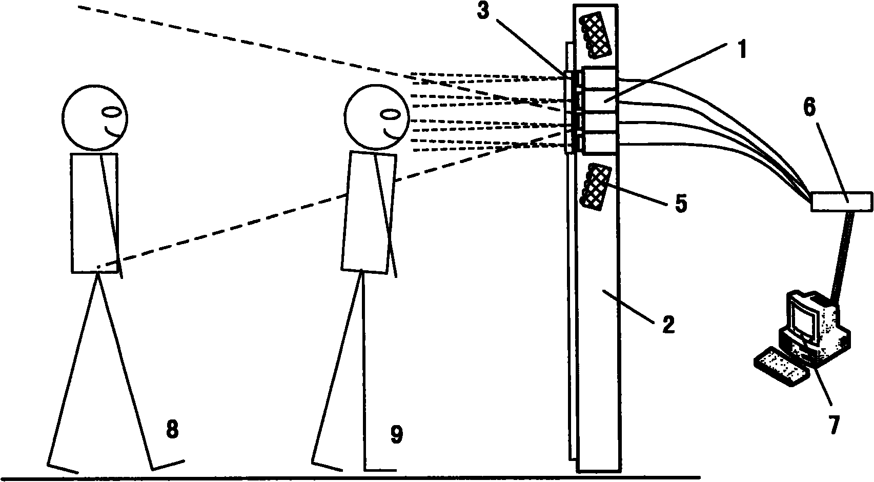
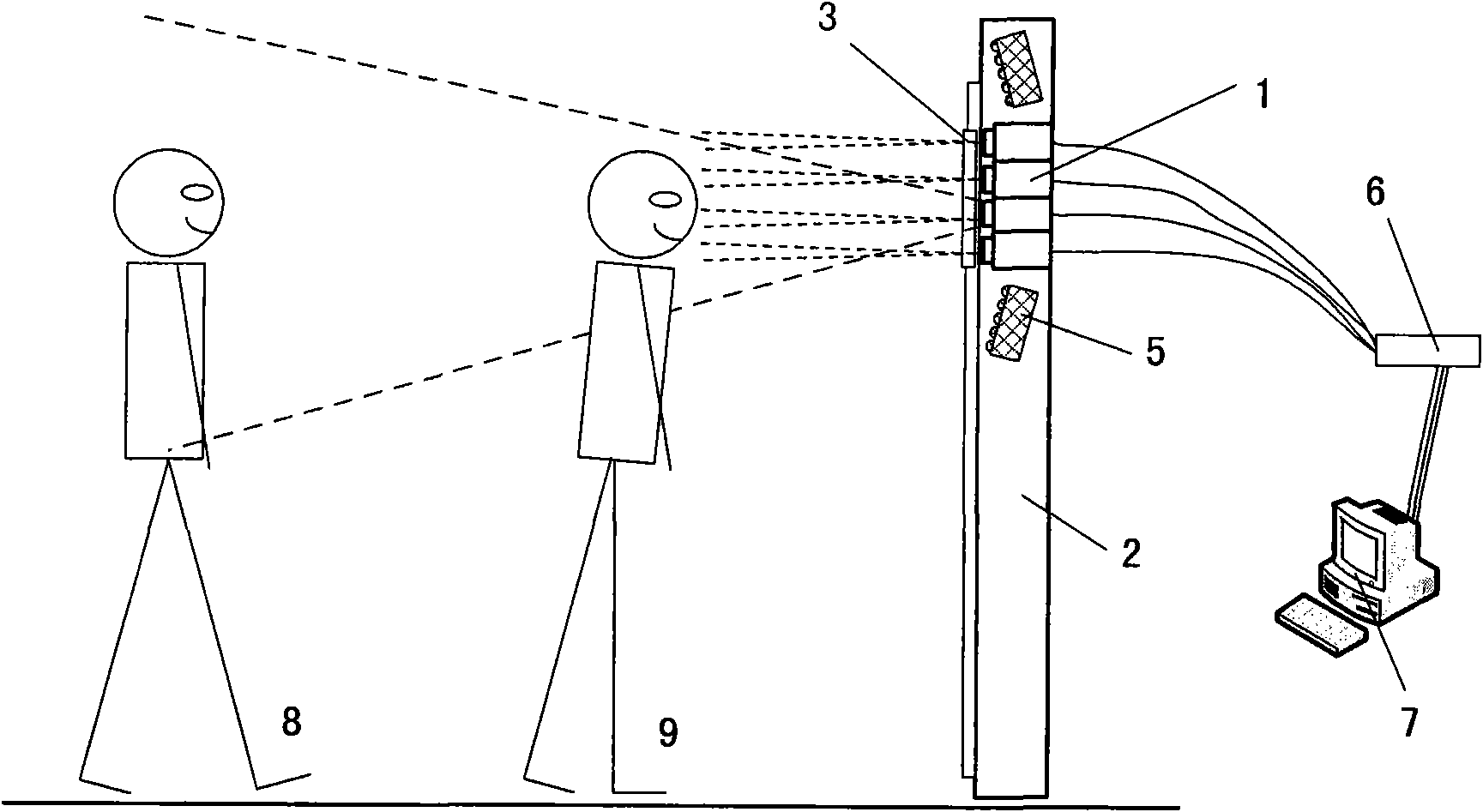
[0069] The basic purpose of the device of the present invention is iris recognition about 1 meter away, and the use process is as follows: the user stands at a position about 1 meter in front of the above-mentioned inventive device, stands naturally, and will find that there are many indicating points; Position Let your eyes align with any point on the mirror, as shown in position 9 in Figure 1. At this time, the integrated camera array behind the mirror starts to focus automatically, and automatically captures the iris image within the depth of field. The person can stand naturally during this process, without moving his eyes from side to side or back and forth, but only needs to align his eyes with one of the indicator points to complete the recognition.

Embodiment 2

[0070] Example 2: Application to "iris-face" multimodal biometric identification

[0071] The camera array device can be used for iris recognition, and the camera can also be controlled to zoom to a wide viewing angle for face recognition, forming an "iris-face" multi-modal biometric recognition system.

[0072] The use process is as follows. When the person is far away from the device, the main camera of the camera array captures the face image; when the person approaches, he needs to point his face at the small mirror, and the camera array captures the iris image; then the system according to the iris- The multi-modal features of the face jointly determine the recognition result.

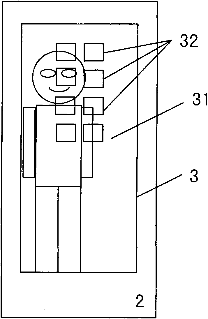
[0073] FIG. 5 is a diagram of the shooting range of each camera: C1-C5 are the cameras forming the camera array 1, and C3 is the main camera. When the person is at a long distance P1, the camera C3 zooms to a wide viewing angle to continuously capture face images, and when a face is detected, fac...

Embodiment 3

[0091] Example 3: Combination of Biometric Identification and Security Monitoring

[0092] We can implement biometric identification and security surveillance at the same time with camera array devices. In the recognition mode, the system prompts people to approach the device for iris recognition or face recognition; in the monitoring mode, the main camera in the camera array zooms to the widest viewing angle, and the computer records its video signal as a surveillance video; In the mode, the voice is used to guide people to move to the front of the mirror, and the narrow viewing angle camera is used to identify people; the recognition mode and monitoring mode can be switched according to different situations.

[0093] Combine iris recognition-face recognition-video surveillance technologies. There are many ways to combine: a) when people carry out iris recognition or face recognition, if repeated attempts are unsuccessful, video cameras can be used to record the video for fu...


PUM


Abstract

The invention relates to an iris identification device by using a camera array and a multimodal biometrics identification method. The system comprises a plurality of cameras, a support structure, an indication unit, a light source, an acquisition card, a computer, and the like, wherein positions of the plurality of cameras can be freely arranged as required. The identification method is implemented according to the following steps that: a person stands naturally and aligns eyes with one of the cameras according to hints; the camera array is started, and each camera starts to acquire images; the computer circularly processes the images of the plurality of cameras at regular intervals and performs human eye detection respectively; and when a human eye image is detected in a path of signal, the path of the image is intensively processed and iris identification is performed. Based on the camera array device, the iris system can acquire iris images at different positions and different heights, so the acquisition range is widened, and the usability of the iris identification system is improved.

Description

technical field [0001] The invention belongs to the technical fields of image processing, pattern recognition, multi-sensor and computer control, and specifically relates to an iris recognition device and method based on a camera array, which are applied in the fields of biological feature recognition and public safety. Background technique [0002] Security technology based on biometric identification is widely used in daily life and in the security field, and has great market application prospects. The goal of biometric identification is to achieve fast and accurate identification or authentication, and it is expected to be applied in the identification of large-scale crowds. [0003] Among biometric identification technologies, iris recognition technology has the advantages of high accuracy, strong uniqueness, and good anti-counterfeiting, which is very suitable for identity authentication of large-scale groups of people. However, the disadvantage of iris recognition is t...

Claims


Application Information

Patent Timeline
Patent Type & Authority Applications(China)
IPC IPC(8): G06K9/00G06K9/20H04N5/225
Inventor 谭铁牛孙哲南董文博谭剑波张小博
Owner INST OF AUTOMATION CHINESE ACAD OF SCI
Why Eureka
Try Eureka