

Method and device for acquiring asymmetric delay time
A delay time and asymmetric technology, applied in the field of communication, can solve the problems of low efficiency and high implementation cost, and achieve the effects of improving efficiency, convenient and accurate acquisition, and convenient time synchronization
- Summary
- Abstract
- Description
- Claims
- Application Information
AI Technical Summary
Problems solved by technology
Method used
Image

Examples
Embodiment 1
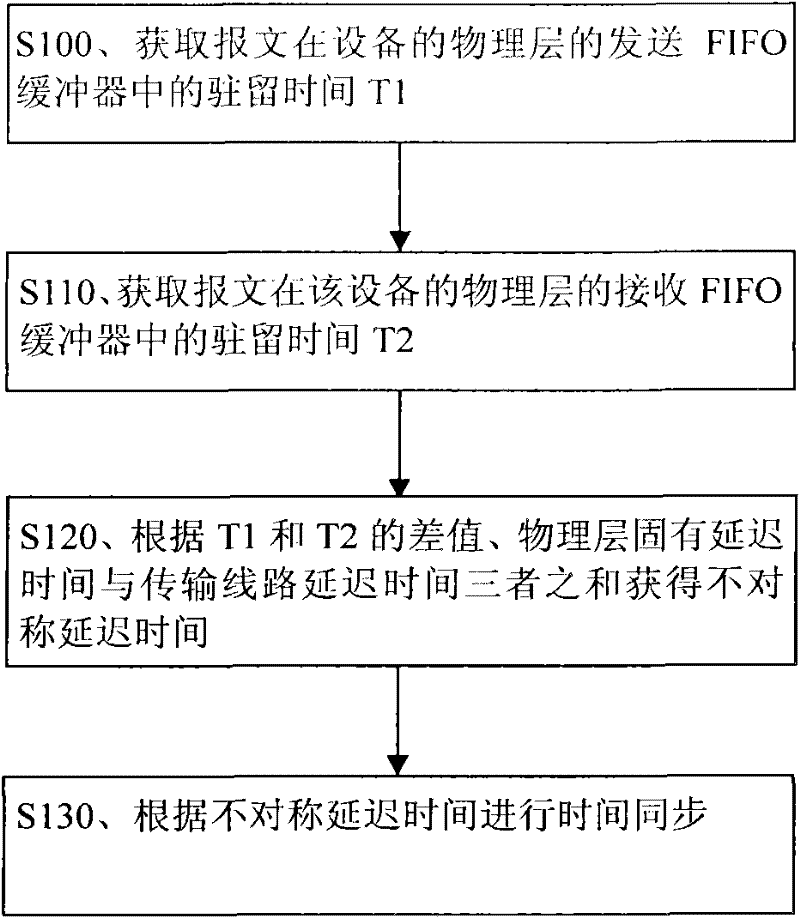
[0027] Embodiment 1. A method for obtaining an asymmetric delay time, comprising: obtaining the residence time T1 of a message in a sending FIFO buffer of a physical layer of a device, and obtaining a receiving FIFO of the message at the physical layer of the device. The dwell time T2 in the buffer; the asymmetrical delay time is obtained according to the sum of the difference between the T1 and T2, the inherent delay time of the physical layer and the transmission line delay time.
[0028] The process of this method is attached figure 1 shown.
[0029] figure 1 In S100, the residence time T1 of the message (for example, the message with a time stamp) in the transmit FIFO buffer of the physical layer of the device is obtained. The device here is a slave device or a responder, etc., specifically, a base station or the like. The above-mentioned transmit FIFO buffer may be a synchronous FIFO (that is, the read clock and the write clock of the transmit FIFO buffer are t...
Embodiment 2
[0067] Embodiment 2: A device for obtaining asymmetric delay time. The apparatus may be a slave device or a responder, etc. Specifically, the apparatus may be a base station or the like. The device is attached figure 2 shown.
[0068] figure 2 The apparatus in FIG. 2 includes: a sending FIFO buffer 200 , a receiving FIFO buffer 210 , a first obtaining module 220 and a second obtaining module 230 , and optionally, the apparatus may further include a time synchronization module 240 .
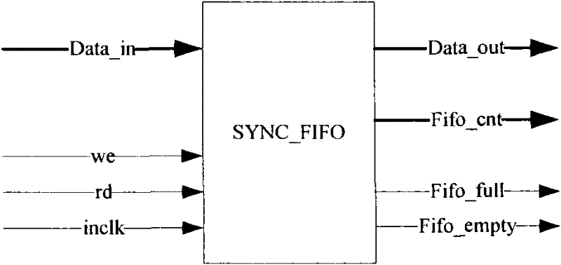
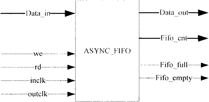
[0069] Both the transmit FIFO buffer 200 and the receive FIFO buffer 210 may be synchronous FIFO buffers or asynchronous FIFO buffers, and the present embodiment does not limit the specific structures and specific models of the transmit FIFO buffer 200 and the receive FIFO buffer 210 .
[0070] The first obtaining module 220 is used to obtain the residence time T1 of the time stamped message in the sending FIFO buffer 200 of the device physical layer, and obtain the receiving FIFO b...
example 1
[0074] Example 1, as attached Figure 2A The illustrated first acquisition module 220 includes: a first timestamp sub-module 221 , a first acquisition depth sub-module 222 , a first count sub-module 223 and a first calculation sub-module 224 . The first counting sub-module 223 includes the first counter described in the foregoing method embodiments.
[0075] The first timestamp submodule 221 is configured to add a timestamp to the event packet when the event packet is sent from the MAC layer to the physical layer. This timestamp is carried in the event message. The first timestamp submodule 221 may be located at the MAC layer, that is, when the first timestamp submodule 221 detects that the MAC layer sends an event packet to the physical layer, it adds a timestamp to the event packet. The first timestamp submodule 221 may also be located at the physical layer, that is, when the first timestamp submodule 221 detects that the physical layer receives an event packet transm...
PUM
 Abstract
Description
Claims
Application Information