Three-dimensional scanner of full automatic lens edge grinding machine

A technology of three-dimensional scanning and edge grinding machine, which is applied to machine tools suitable for grinding workpiece edges, parts of grinding machine tools, grinding machines, etc., and can solve the problems of three-dimensional data processing of lenses and mirror frames.

Active Publication Date: 2011-10-05
EAST CHINA INST OF OPTOELECTRONICS INTEGRATEDDEVICE +1
View PDF0 Cites 0 Cited by
  • Summary
  • Abstract
  • Description
  • Claims
  • Application Information

AI Technical Summary

Problems solved by technology

[0003] The technical solution of the present invention is to solve the defects existing in the existing edging machine that cannot perform three-dimensional data processing on the lens and the frame, and provide a three-dimensional scanning device for the fully automatic lens edging machine

Method used


Image

  • Three-dimensional scanner of full automatic lens edge grinding machine
  • Three-dimensional scanner of full automatic lens edge grinding machine
  • Three-dimensional scanner of full automatic lens edge grinding machine

Examples


Embodiment Construction

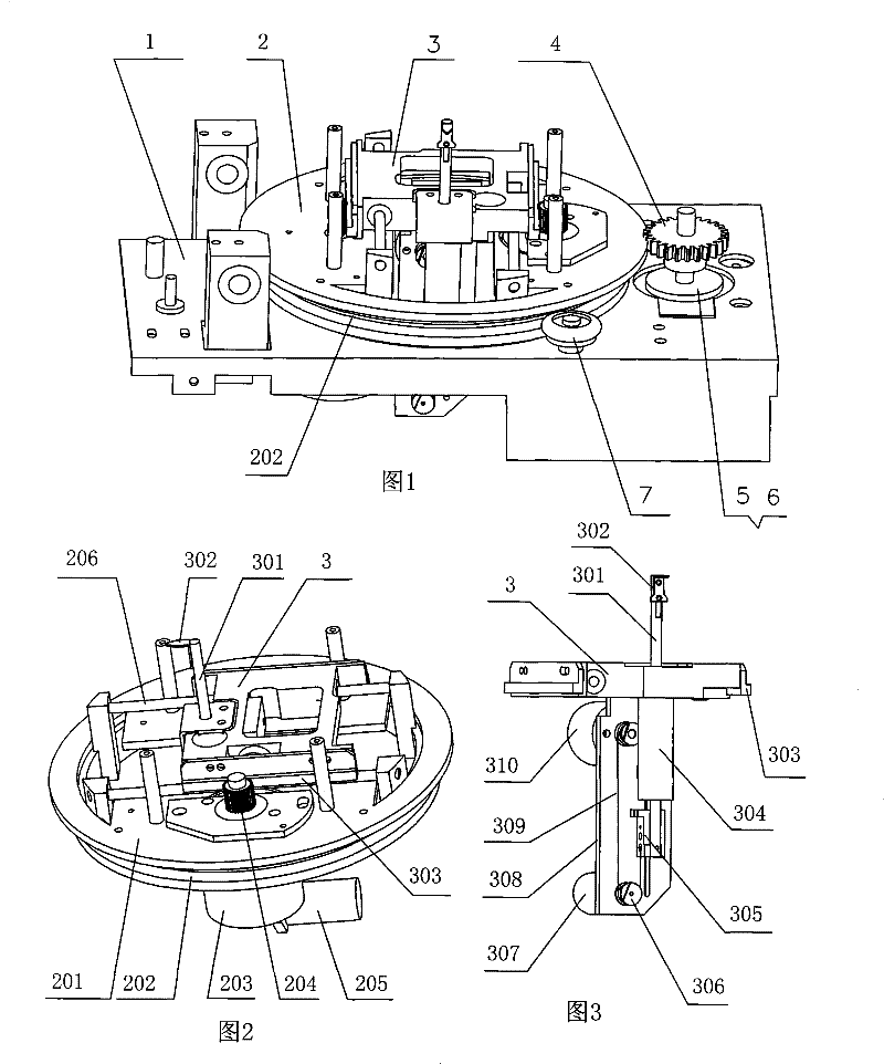
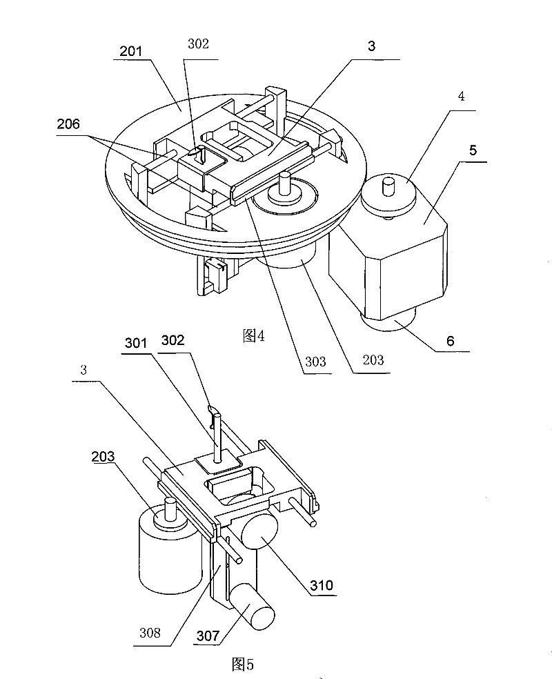
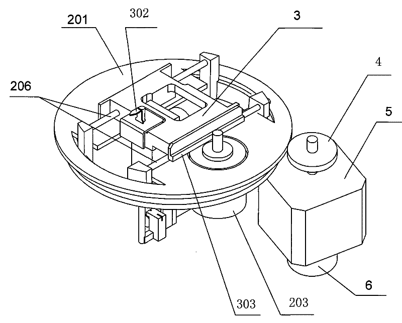
[0017] The three-dimensional scanning device of the automatic lens edging machine provided by the present invention mainly includes:

[0018] see figure 1 , figure 2 :

[0019] A base 1, which is installed in the edging machine, a set of supporting wheels 7 and a circumferential motor 5 are arranged in the base according to the concentric circle distribution, and one end of the circumferential motor 5 is connected to an encoder 6, and the other end is connected to a circumferential gear 4. The circumferential motor 5 and the encoder 6 are in figure 1 is blocked, as shown in 4. The number of the set of supporting wheels 7 is more than three, subject to the ability to support the scanning platform 2 , when the circumferential motor 5 rotates, the circumferential data can be obtained through the encoder 6 .

[0020] A disk-shaped scanning platform 2, the edge of the scanning platform is provided with gear teeth and the circumferential gear 4 on the circumferential motor to c...


PUM


Abstract

The invention relates to a three-dimensional scanning device used for an automatic eyeglass edger, comprising a circumferential motor (5) which is arranged on a base, an encoder (6) and a scanning platform (201); the three-dimensional scanning device is driven with the gear (4) of the circumferential motor in a matching way; the scanning platform is provided with a radial motor (203), an encoder and a trolley (3) which are connected with each other; the three-dimensional scanning device is matched with a guide column (206) in a sliding way; the edge of the trolley is provided with a rack (303) which is driven with the radial gear which is connected with the radial motor in a matching way; the trolley is provided with a height motor, an encoder and a lifting probe (302). The automatic positioning three-dimensional scanning to the picture frame or eyeglass templates is completed by collecting the signals of the circumferential motor and height motor, the radial motor and the encoder thereof. The three-dimensional scanning device has the advantages that the three-dimensional data of the eyeglass or the eyeglass frame can be exactly and conveniently gained and converted into control data by data processing, thus completing the precise processing of eyeglass.

Description

technical field [0001] The invention relates to a fully automatic lens edging machine, in particular to an automatic positioning three-dimensional scanning device for collecting three-dimensional data on the shape of a spectacle frame or a lens template that needs to be processed. Background technique [0002] The product development of lens edging machines in the domestic glasses production industry is relatively backward. The leading product is semi-automatic lens edging machines with molds. The working process is to complete the lens shape grinding and cutting process by copying the shape of the lens template. The working principle of the semi-automatic molded lens edger machine determines that it can only perform two-dimensional profiling scanning on the lens template, that is, the simple processing of the angle and radial data of the lens, which makes the processing accuracy low and cannot guarantee the accuracy of lens grinding. Accuracy requirements. In addition, the...

Claims


Application Information

Patent Timeline
Patent Type & Authority Patents(China)
IPC IPC(8): B23Q35/24B24B9/14B24B49/00
Inventor 周晓丹刘义兵邓闯孙帮东姚鑫刘培群孙昭史予
Owner EAST CHINA INST OF OPTOELECTRONICS INTEGRATEDDEVICE
Why Eureka
Try Eureka