A non-contact fluid film thickness measurement device and method
A fluid film and thickness measurement technology, applied in the research field of fluid measurement technology, can solve problems such as large measurement errors, interference, and destruction of fluid flow fields, and achieve good versatility and flexibility
- Summary
- Abstract
- Description
- Claims
- Application Information
AI Technical Summary
Problems solved by technology
Method used
Image
Examples
Embodiment
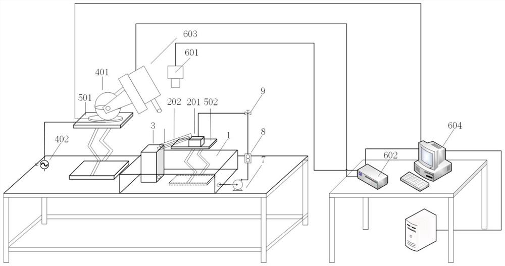
[0049] A non-contact fluid film thickness measurement device, such as figure 1 As shown, it includes a liquid storage tank 1, a lift, an overflow weir 201, a liquid flow channel 202, a recovery box 3, an adjustable angle loading platform 4, and a LIF system 6;
[0050] The liquid storage tank is sequentially connected to a water pump 7, a flow meter 8, a valve 9, and an overflow weir 201 through a pumping pipeline;
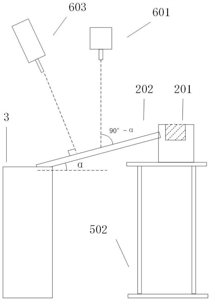
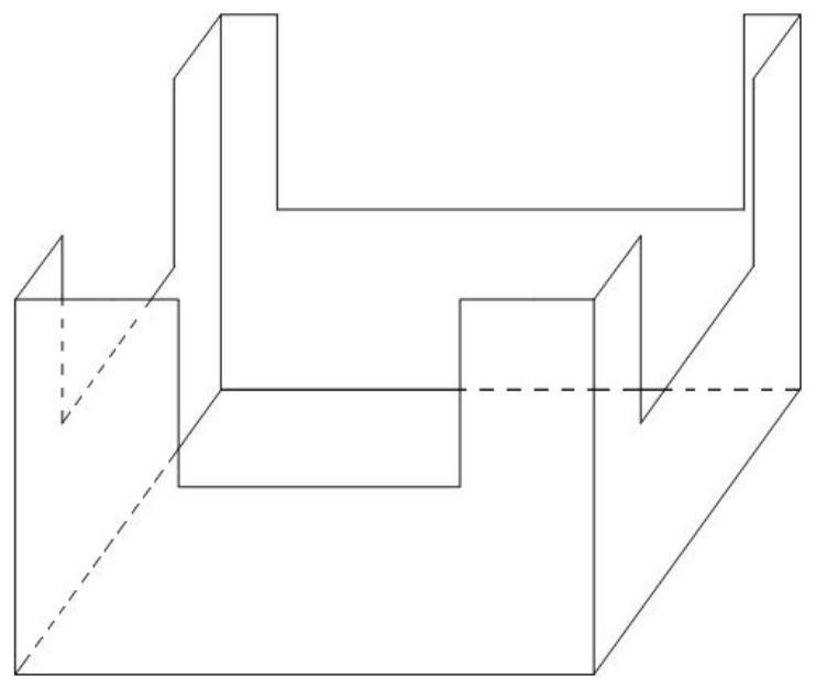
[0051] The liquid storage tank 1 is connected to the liquid flow channel 202 through the U-shaped outlet on the side wall of the overflow weir, and the fluid flowing through the liquid flow channel 202 flows into the recovery tank 3 and then flows into the liquid storage tank 1 again; that is, the liquid storage tank 1 Used to provide and receive experimental fluids; figure 2 is a partial enlarged view of the measuring part of the measuring device; image 3 is the side view of the overflow weir structure; Figure 4 is the right view of the recycling bin struct...
Embodiment 2
[0059] A non-contact fluid film thickness measurement method, such as Figure 7 shown, including the following steps:
[0060] S1. Add the configured fluid containing a certain concentration of dyeing agent in the liquid storage tank 1. The fluid containing a certain concentration of dyeing agent is an aqueous rhodamine B solution with a concentration of 0.2g / L and a maximum absorption light intensity of 545nm. The maximum fluorescence intensity is 580nm;
[0061] Select the shooting angle of view above the liquid flow channel 202, and place the laser generator 603 of the LIF system 6 on the oblique top of the liquid flow channel 202 to be 90 degrees relative to the liquid flow channel 202; place the CCD camera 601 of the LIF system 6 The relative position above the liquid flow channel 202 and the liquid flow channel 202 is at an angle of 90°-α, and a long-pass filter is used;
[0062] S2. Take ten equidistant lines in the lateral direction of the inclined surface in the cal...
PUM
 Abstract
Description
Claims
Application Information
 - R&D
- Intellectual Property
- Life Sciences
- Materials
- Tech Scout
- Unparalleled Data Quality
- Higher Quality Content
- 60% Fewer Hallucinations
Browse by: Latest US Patents, China's latest patents, Technical Efficacy Thesaurus, Application Domain, Technology Topic, Popular Technical Reports.
© 2025 PatSnap. All rights reserved.Legal|Privacy policy|Modern Slavery Act Transparency Statement|Sitemap|About US| Contact US: help@patsnap.com


