

Humidity control device and ventilation device
A technology for humidity regulation and air, applied in air conditioning systems, gas treatment, climate sustainability, etc., can solve problems such as cumbersome maintenance
- Summary
- Abstract
- Description
- Claims
- Application Information
AI Technical Summary
Problems solved by technology
Method used
Image

Examples
no. 1 approach
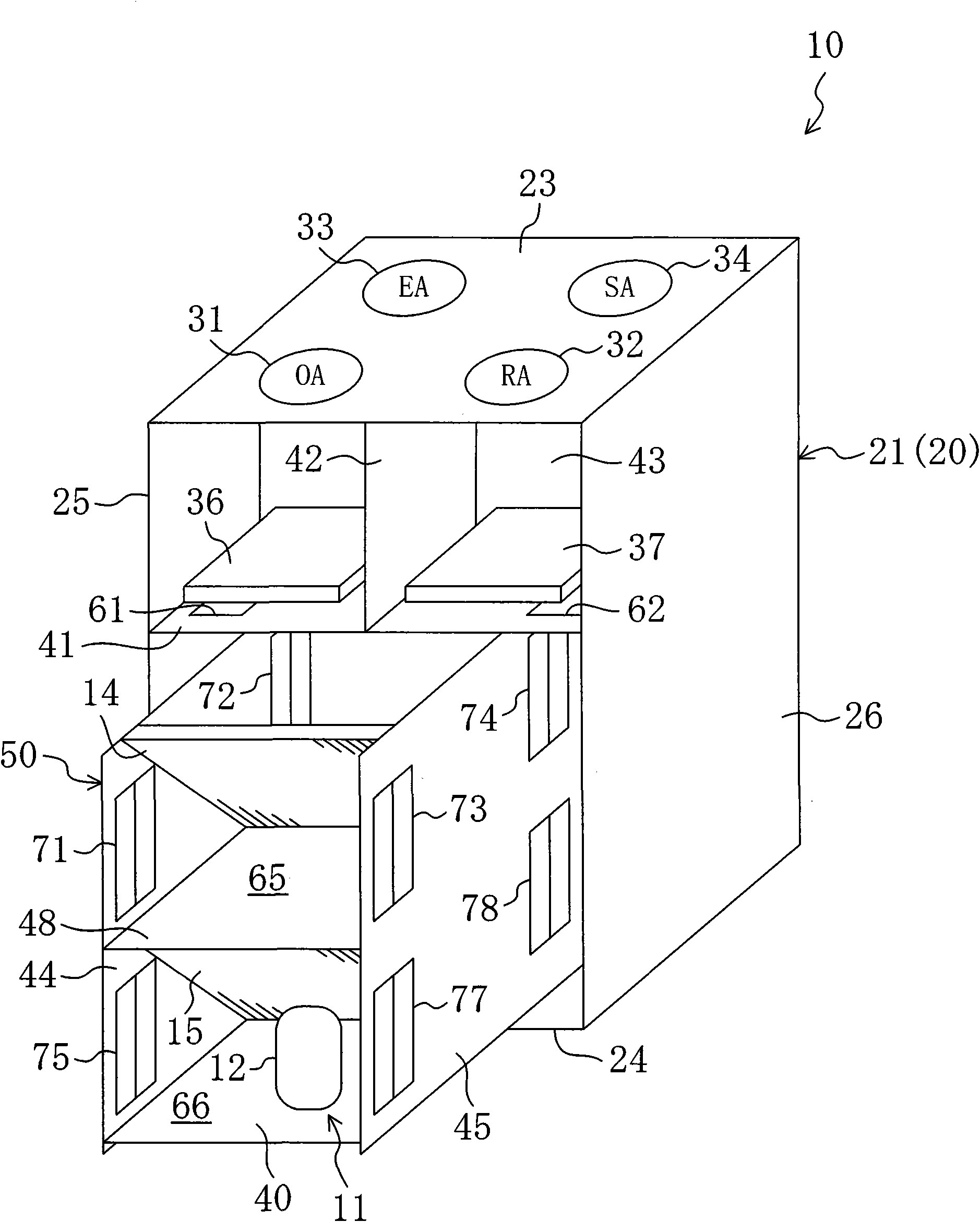
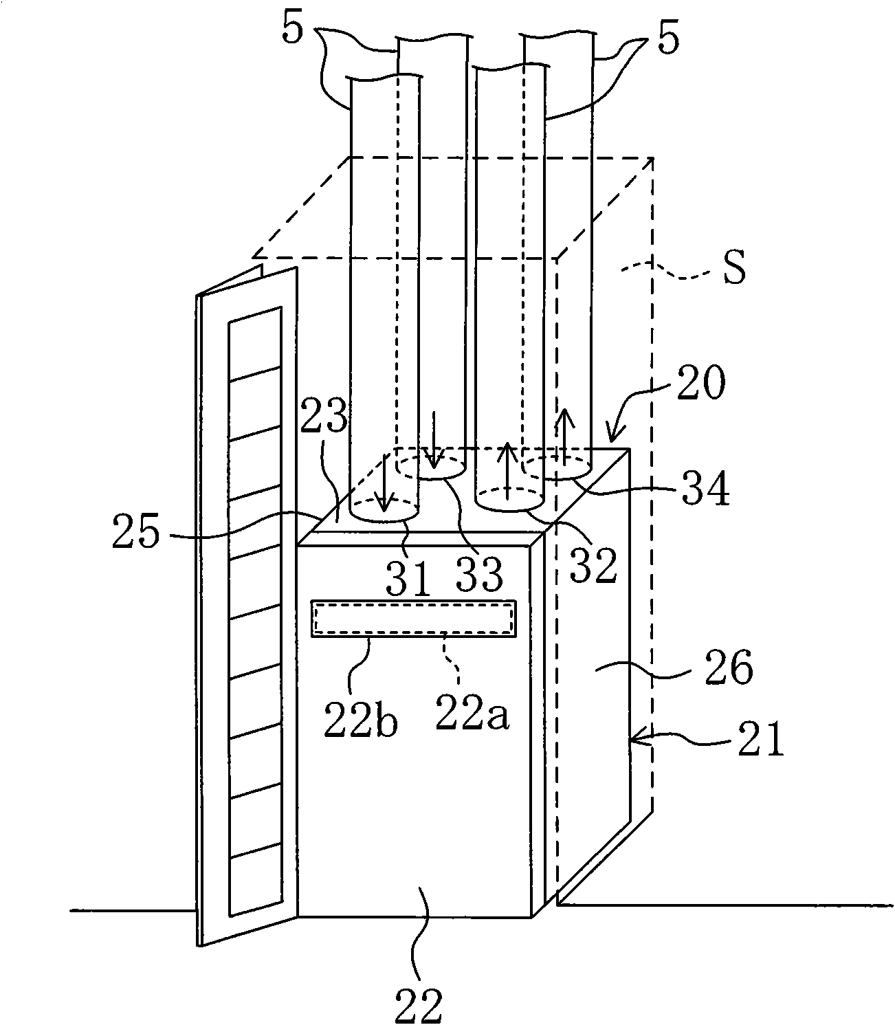
[0123] The humidity control device 10 according to the first embodiment of the present invention is a floor-standing humidity control device that is installed on a floor surface of a room to control indoor humidity. As shown in FIG. 1 , the humidity control device 10 is configured to be installed in a storage space S of a cabinet for storing clothes and the like.
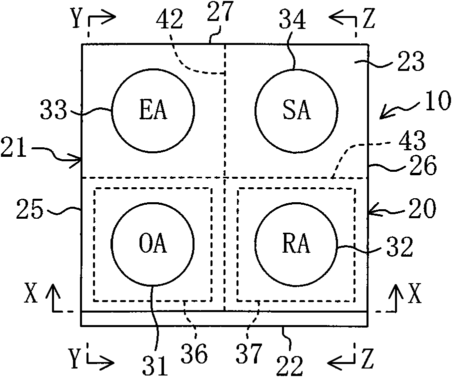
[0124] As shown in FIGS. 1 to 3 , the humidity conditioner 10 has a casing 20 formed in a vertically elongated rectangular parallelepiped shape. In addition, in the perspective view (also including other perspective views) of FIG. 3 , for convenience of illustration, the upper part of the housing 20 is shown separately from other parts. The housing 20 includes a box-shaped housing main body 21 with only the front open, and a front cover 22 detachably attached to the opening on the front side of the housing main body 21 .
[0125] A top plate 23 is formed at an upper end portion of the case main body portion 21 , an...
no. 2 approach
[0210] The structure of the humidity control apparatus 10 which concerns on 2nd Embodiment differs from the said 1st Embodiment. Hereinafter, differences from the first embodiment will be mainly described. The humidity control device 10 according to the second embodiment has a vertically flat casing 20 and is installed on, for example, the back surface of a ceiling.
[0211] As shown in Figure 11, an outdoor suction port 31 is formed at the lower part of the central part of the front side (upper side in Figure 11(A)) of the housing 20, and an indoor suction port 31 is formed at the upper part of the central part of the front side. Mouth 32. In addition, an outdoor exhaust port 33 is formed at the rear of the left side of the casing 20, and an indoor air supply port 34 is formed at the rear of the right side thereof. Further, a side cover 28 detachably attached to the case main body 21 is attached to the right side of the case 20 .
[0212] The inside of the casing 20 is par...
no. 3 approach
[0222] The structure of the humidity control apparatus 10 which concerns on 3rd Embodiment of this invention differs from the said 1st Embodiment and 2nd Embodiment. The humidity control device 10 according to the third embodiment is a device that dehumidifies and humidifies air using a rotatable dehumidification rotor 80 . In addition, the humidity control device 10 in this example is configured as a ventilating type that adjusts the humidity of the outdoor air OA, supplies the outdoor air OA as the supply air SA to the room, and discharges the room air RA to the outside as the exhaust air EA. Humidity regulator.
[0223] Specifically, as shown in FIG. 13 , the humidity control device 10 defines a first air passage 91 and a second air passage 92 in the casing 20 . The outdoor suction port 31 is formed on the inflow side of the first air passage 91 , and the indoor air supply port 34 is formed on the outflow side of the first air passage 91 . Furthermore, the indoor suction ...
PUM
 Abstract
Description
Claims
Application Information