
Jack-knife bridge

A bridge body and fixed bridge body technology, applied in floating bridges, bridges, bridge forms, etc., can solve the problems of inability to pass through large ship structures, impassability of pedestrians and vehicles, and high cost, so as to improve the efficiency of bridge erection, save assembly links, The effect of reducing the construction cost

Inactive Publication Date: 2010-09-01
关佩萌 +1
View PDF0 Cites 7 Cited by
  • Summary
  • Abstract
  • Description
  • Claims
  • Application Information

AI Technical Summary

Problems solved by technology

Especially to solve the shortcomings of the existing open bridge in the prior art that pedestrians and vehicles cannot pass when it is in the open state, and the shortcomings that the foldable bridge cannot pass large ships when it is working, and the structure is complex and the cost is high.

Method used


Image

  • Jack-knife bridge
  • Jack-knife bridge
  • Jack-knife bridge

Examples


Embodiment 1

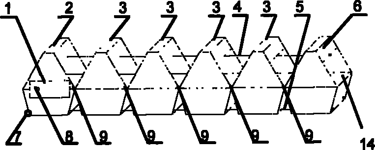
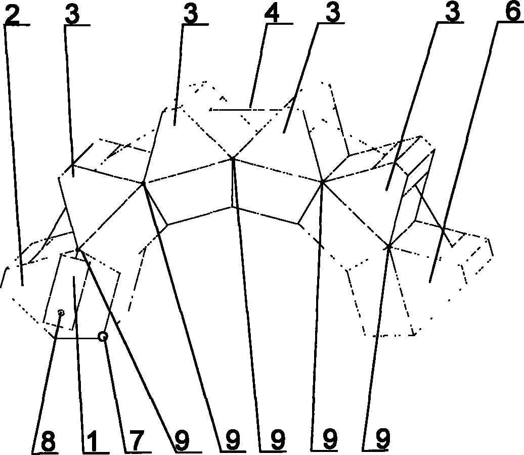
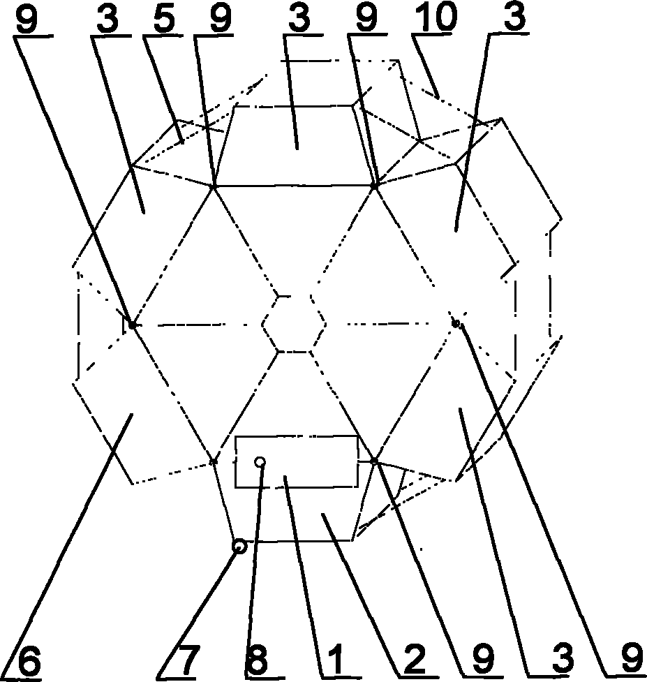
[0045] Embodiment 1 of the present invention proposes a folding bridge, such as figure 1 As shown, the folding bridge includes a fixed bridge body wedge 2 connected to the ground, wherein in an embodiment of the present invention, the fixed bridge body wedge 2 can be connected to the ground through a rotating secondary hinge 7, of course, those skilled in the art will also Can be connected in other ways. This folding bridge also comprises floating bridge body wedge 6, and a plurality of intermediate bridge body wedges 3 that are connected between the fixed bridge body wedge 2 and the floating bridge body wedge 6, the intermediate bridge body wedge 3 is mutually and The fixed bridge body wedge block 2, the floating bridge body wedge block 6 and the intermediate bridge body wedge block 3 are connected by connecting rotary joint hinges. The bridge deck 14 that can allow cars, bicycles, pedestrians, etc. to pass is located at the middle horizontal position of the wedge blocks 2 ,...

Embodiment 2

[0054] This embodiment is different from Embodiment 1 in that in this embodiment the driving device includes a second driving motor 14 and a second cable shaft 12 driven by the second driving motor 14, and a third driving motor 13 and a third driving motor 13. The third cable shaft 11 driven by the drive motor 13, the upper cable 4 is connected to the second cable shaft 12, the first pull cable 5 and the second pull cable 10 are connected to the third cable shaft 11, And the winding direction of the upper pull cable 5 is opposite to that of the first pull cable 5 and the second pull cable 10, as Figure 5 and 6 shown. In this embodiment, the working mode of the folding bridge is the same as that in Embodiment 1, and will not be repeated here. As a preferred embodiment of the present invention, it also includes a controller that controls the driving of the second driving motor 14 and the driving of the third driving motor 13, so that the second driving motor 14 and the third ...


PUM


Abstract

The invention discloses a jack-knife bridge, which comprises a fixed bridge body wedge block, a floating bridge body wedge block, a plurality of intermediate bridge body wedge blocks, a driving device, an upper guy cable, a first lower guy cable and a second lower guy cable, wherein the winding direction for connecting the upper guy cable and the first lower guy cable is opposite to the winding direction for connecting the second lower guy cable and the driving device; and the driving device drives the upper guy cable, the first lower guy cable and the second lower guy cable so as to control the state of the jack-knife bridge. Apart form the advantages of quick transportation and bridging of the jack-knife bridge, the jack-knife bridge provided by the embodiment of the invention has the advantages of an open bridge that the width and headroom of the bridge can be properly adjusted for ships under the bridge so that the ships of different sizes can pass through the bridge; and in addition, the jack-knife bridge has the characteristics of simple structure, rational stress, no need of overmuch hydraulic unit driving and greatly reduced construction cost. The invention also provides a jack-knife bridge system.

Description

technical field [0001] The invention relates to the technical field of bridge design, installation and manufacture, in particular to a folding bridge. Background technique [0002] With the continuous progress of society and the continuous development of technology, transportation has become more and more convenient, but at the same time, the busy traffic also puts forward higher requirements for the design and manufacture of transportation facilities. According to whether the bridge body can move, the current bridges can be divided into two categories: fixed bridges and mobile bridges. The bridge body of the fixed bridge is fixed and cannot be deformed or moved, so that the working environment and functions of the fixed bridge are relatively fixed. However, as the traffic becomes more and more complex, not only the vehicles and pedestrians passing through the bridge must be considered, but also enough width and clearance should be left for the ships under the bridge, and t...

Claims


Application Information

Patent Timeline
Patent Type & Authority Applications(China)
IPC IPC(8): E01D15/20
Inventor 关佩萌关立文
Owner 关佩萌
Learn More