Adjustable hanger system

An adjustable and hanging technology, applied in the connection of scaffolding, formwork/formwork/work frame, scaffolding supported by house structure, etc. Effects of reuse, improved safety, and labor liberation

Active Publication Date: 2010-09-01
CHINA CONSTR THIRD ENG BUREAU GRP CO LTD +1
View PDF6 Cites 10 Cited by
  • Summary
  • Abstract
  • Description
  • Claims
  • Application Information

AI Technical Summary

Problems solved by technology

[0004] The purpose of the present invention is to provide an adjustable hanger system, to solve the problem that the original hanger system cannot freely adjust the height, does not realize standardized operation, cannot be used repeatedly on different buildings, cannot be adjusted with the height of the building, It can only be the problem of setting up hangers of different sizes according to different buildings, and solve the problems of low safety of the hanger system, large labor consumption for erection of hangers, and high cost of erection of the hanger system

Method used


Image

  • Adjustable hanger system
  • Adjustable hanger system
  • Adjustable hanger system

Examples


Embodiment 1

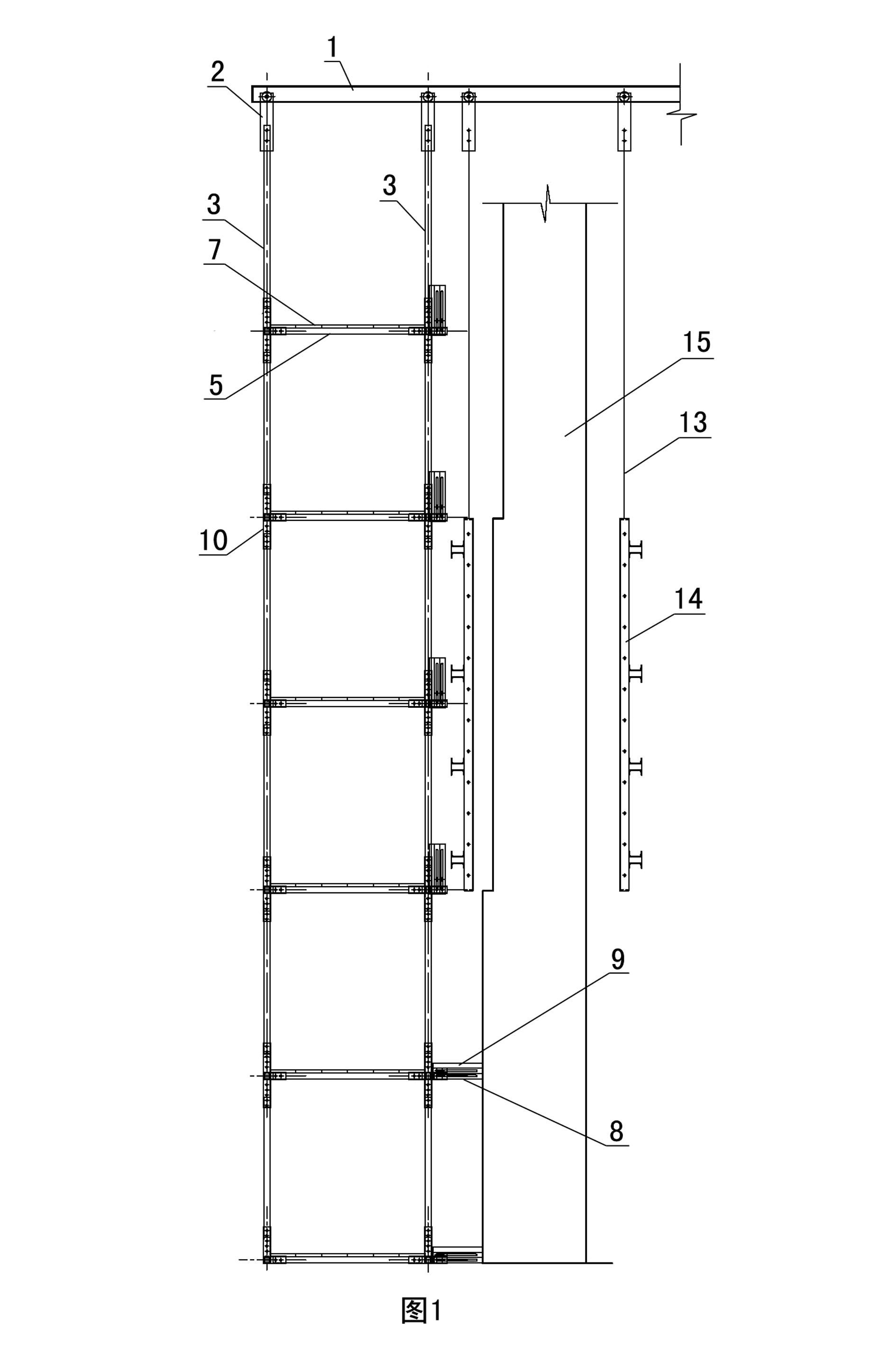
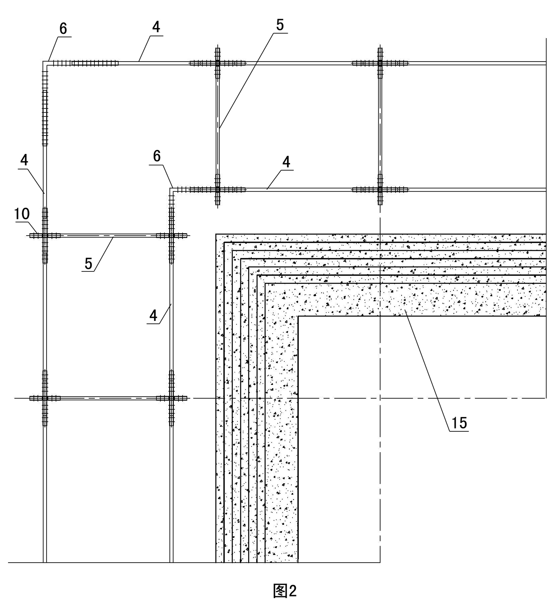
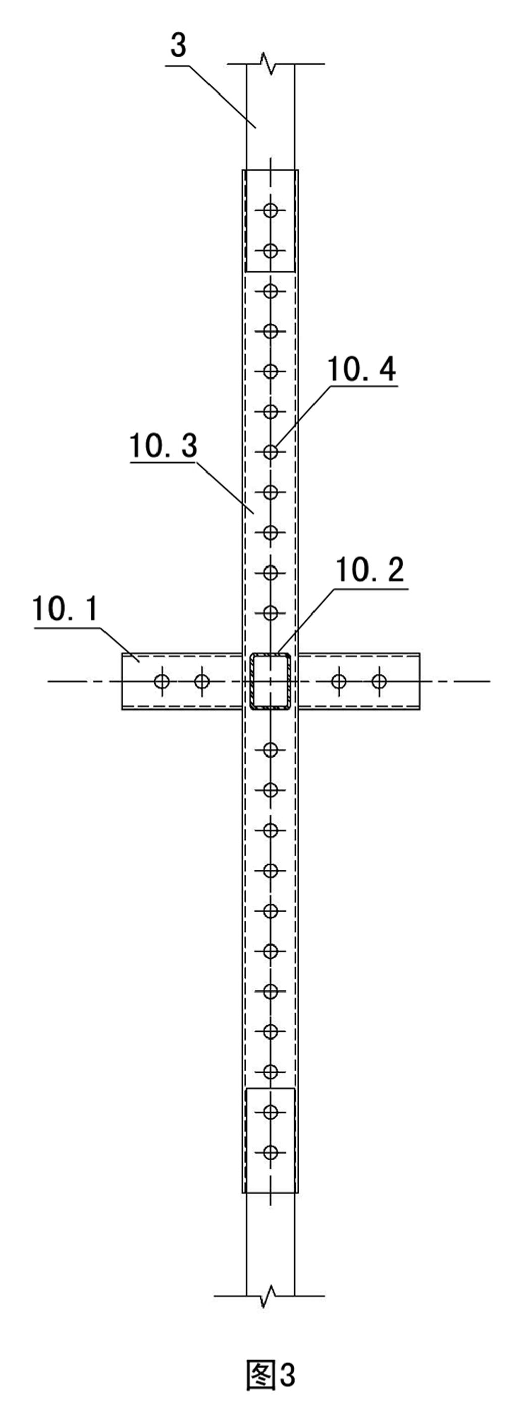
[0028] Embodiment one sees Figure 1-4 As shown, this adjustable hanger system includes a skeleton connected to the steel platform system and a steel springboard 7 fixed on the skeleton. The inner and outer sheet connecting rods 5 form a three-dimensional grid structure, and the inner sheet of the hanger and the outer sheet of the hanger all include suspenders 3, horizontal cross bars 4 and shaped joint pipes 10 at the nodes at intervals, and the suspenders 3, Horizontal bar 4 and inner and outer sheet connecting rod 5 can be square steel pipe or round steel pipe or flat steel, and the present embodiment is square steel pipe. see image 3 , Figure 4 The shaped joint pipe 10 is evenly distributed with screw holes 10.4, and is welded by a horizontal pipe joint 10.1, a vertical pipe joint 10.2 and a vertical pipe joint 10.3. The shaped joint pipe 10 can be a square steel pipe or a round steel pipe or a flat steel. This implementation For example, a square steel pipe, the vert...

Embodiment 2

[0029] Embodiment two see Figure 12 As shown, the difference from Embodiment 1 is that the push-pull platform slideway 8 is in the shape of a guide rail, and a corbel 11 is connected between the lower surface of the push-pull platform slideway 8 and the inner sheet of the hanger, and the push-pull platform slideway 8 A diagonal brace 12 is connected between the upper surface and the inner sheet of the hanger, and the push-pull turning platform 9 is directly placed on the slideway 8 of the push-pull platform and slides along the slideway 8 of the push-pull platform.

[0030] The distance between the suspender 3 and adjacent suspenders is 1m-2m, and the distance between the inner piece of the hanger and the outer piece of the hanger is also 1m-2m. The horizontal pipe joint 10.1, the vertical pipe joint 10.2 and the vertical pipe joint 10.3 of the shaped joint pipe 10 are each provided with two or more screw holes 10.4.

[0031] see figure 1 , Figure 5 , Image 6 , the shap...


PUM


Abstract

The invention discloses an adjustable hanger system, which comprises a framework connected with a steel platform system and a steel jump plate fixed on the framework. The framework has a three-dimensional pane structure consisting of an inner hanger sheet, an outer hanger sheet and an inner and outer sheet connecting rod connected between the inner hanger sheet and the outer hanger sheet; both the inner hanger sheet and the outer hanger sheet comprise a suspender, a horizontal cross rod and a shaped joint tube at a node, which are arranged at intervals; and screw holes are uniformly distributed on the shaped joint tube, and the shaped joint tube is welded by a transverse tube joint, a longitudinal tube joint and a vertical tube joint, wherein the vertical tube joint is detachably connected with the inner and outer sheets through bolts, the transverse tube joint is detachably connected with the horizontal cross rod through bolts, and the longitudinal tube joint is detachably connected with the inner and outer sheet connecting rod through bolts. The hanger system can be widely applied to mounting construction of a high-rise concrete core tube structure of formwork creeping or lifting system construction, a steel structure and the like. The hanger system can meet the requirements of different buildings, realizes integral standardized operation, liberates a large amount of labor force, reduces the cost, and improves the safety of a hanger.

Description

technical field [0001] The invention relates to a hanger system used in a climbing formwork system of a super high-rise building. Background technique [0002] At present, the operating layer of the climbing formwork system used in the construction of super high-rise buildings generally adopts a hanger or a bracket system, wherein the hanger generally has 5 to 6 layers, and the height of each layer can be designed according to the height of the building; the hanger's The suspender generally adopts square steel pipe or angle steel, and the suspender needs to be supported in place at one time according to the height of the hanger; the operating space between the hanger and the shear wall is closed with steel mesh, and the steel mesh is cable-stayed and hung by a noose cable. Frame connection, the cable-stayed angle of the noose can be adjusted accordingly according to the change in the width of the operating space. [0003] In the construction of super high-rise buildings, be...

Claims


Application Information

Patent Timeline
Patent Type & Authority Applications(China)
IPC IPC(8): E04G3/28E04G11/28E04G7/14
Inventor 张琨黄刚吴延宏唐浩何穆杨婧孙玉林许立艾白进松王开强刘晓升黄爽刘志茂王伟唐静
Owner CHINA CONSTR THIRD ENG BUREAU GRP CO LTD
Why Eureka
Try Eureka