Template connecting piece capable of regulating and controlling angle

A technology for connectors and templates, which is applied to the connectors of formwork/formwork/work frame, the preparation of building components on site, construction, etc., which can solve the problems of affecting the appearance quality of concrete, inaccurate angle setting, and leakage of concrete grout, etc. problems, achieve rapid installation and disassembly, simple structure, and improve quality

Inactive Publication Date: 2010-09-01
HOHAI UNIV
View PDF0 Cites 8 Cited by
  • Summary
  • Abstract
  • Description
  • Claims
  • Application Information

AI Technical Summary

Problems solved by technology

This method can easily deform the formwork at the joints, resulting in leakage of concrete grout, inaccurate angle setting, and affecting the appearance quality of concrete

Method used


Image

  • Template connecting piece capable of regulating and controlling angle
  • Template connecting piece capable of regulating and controlling angle
  • Template connecting piece capable of regulating and controlling angle

Examples


Embodiment 1

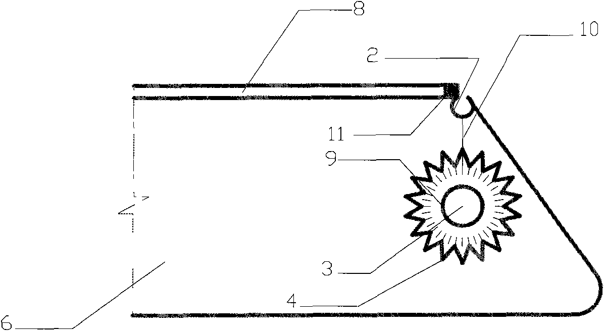
[0022] Such as figure 1 , 2 , 3, 4 and 7 can be used for the chamfering construction of formwork with chamfers in the range of 150° to 240°.

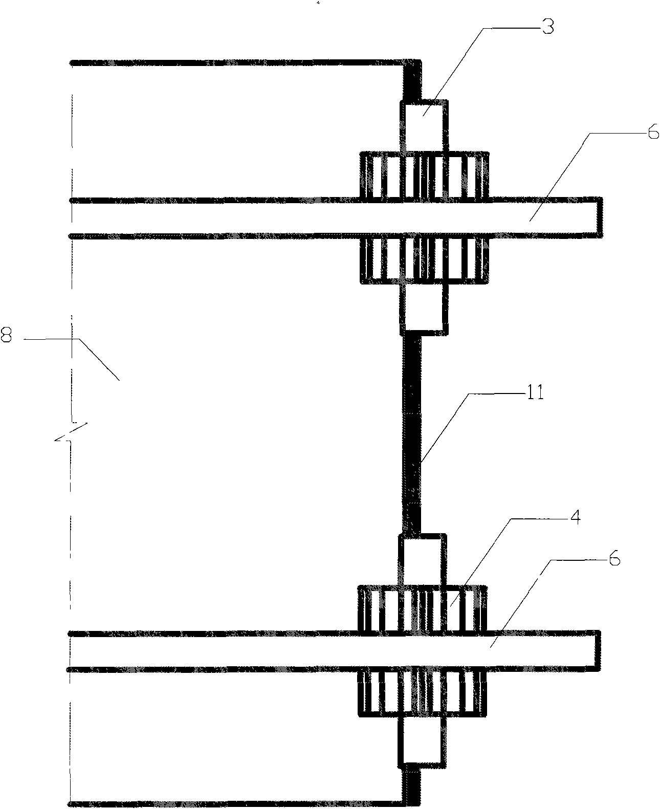
[0023] The first sub-component 5 is connected with the connection rotation shaft penetration hole 2 on the second sub-component 6 by means of the connection rotation shaft 1, which can be connected temporarily or permanently, depending on the needs of the work. The template 8 is provided with a rubber bead 11 on the chamfered contact edge, and the first and second sub-components 5 and 6 are arranged on the template 8 along the chamfered boundary; the angle adjustment gear 4 is set on the gear rotating shaft 3 . Butt the second sub-member 6 with the first sub-member 5, when the saw teeth on the gear just mesh, read the reading of the relative scale gauge 9 relative to the standard scale line 10, and calculate the scale corresponding to the angle adjustment gear when the angle to be flipped is reached , rotate the second sub-component 6...

Embodiment 2

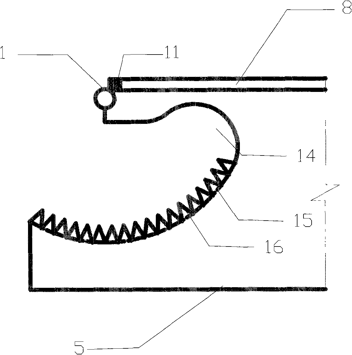
[0030] Such as Figure 5 , 6 As shown in and 7, it can be used for chamfering construction of formwork with chamfers in the range of 0°~150°.

[0031] The first sub-component 5 is connected with the connection rotation shaft penetration hole 2 on the second sub-component 6 by means of the connection rotation shaft 1, which can be connected temporarily or permanently, depending on the needs of the work. The template 8 is provided with a rubber bead 11 on the chamfered contact edge, and the first and second sub-components 5 and 6 are arranged on the template 8 along the chamfered boundary; the angle adjustment gear 4 is set on the gear rotating shaft 3 . Butt the second sub-member 6 with the first sub-member 5, when the saw teeth on the gear just mesh, read the reading of the relative scale gauge 9 relative to the standard scale line 10, and calculate the scale corresponding to the angle adjustment gear when the angle to be flipped is reached , rotate the second sub-component ...


PUM


Abstract

The invention relates to a template connecting piece capable of regulating and controlling an angle. The template connecting piece can measure and regulate the angle in a range of 0 to 240 degrees in template construction rapidly and lock immediately, and can be used for quickly setting the included angle of a bracket bridging. The template connecting piece consists of two sub-components and a locking device. A using method comprises the following steps of: assembling the sub-components to form a rotating system; fixing the sub-components on a template; calculating a corner and rotating the subcomponents; and locking the sub-components after reaching a required angle so as to fulfill the aim of setting a chamfer angle. The template connecting piece has the advantages of wide application, simple connecting piece mode, simple and intuitive method for reading corner reading, confirm support without adverse phenomena of template distortion, concrete slurry outleakage or the like, good concrete cast appearance quality, repeated use, fast assembly and disassembly, quickness and convenience,, simple operation procedure, and great improvement on construction speed.

Description

technical field [0001] The invention relates to a connecting piece used in formwork engineering, in particular to a formwork connecting piece capable of measuring and adjusting angles within a certain range and using a self-locking device to lock the angle. Background technique [0002] In order to reduce stress concentration and ensure the appearance quality of concrete, certain chamfering structures are often encountered during the design and construction of concrete structures. In the actual construction process, in addition to 90° chamfering, other angles of chamfering will also be used. At present, construction units often use two formworks for temporary splicing. Bolts or pressure are used to fix the formwork between the formwork, and square wood is used to support the side formwork on the outside of the formwork. Such an approach can easily deform the formwork at the joints, resulting in leakage of concrete grout, inaccurate angle setting, and affecting the appearance...

Claims


Application Information

Patent Timeline
Patent Type & Authority Applications(China)
IPC IPC(8): E04G17/075
Inventor 冯淑珍吴继敏崔海
Owner HOHAI UNIV
Why Eureka
Try Eureka