
LED anti-dazzle lamp

An LED anti-glare lamp and reflective plane technology, applied in the field of LED lamps, can solve the problems of high cost, large loss of light from transparent parts, complicated procedures, etc., and achieve the effects of low energy loss, low cost and simple structure

Inactive Publication Date: 2010-09-01
OCEANS KING LIGHTING SCI&TECH CO LTD +1
View PDF5 Cites 1 Cited by
  • Summary
  • Abstract
  • Description
  • Claims
  • Application Information

AI Technical Summary

Problems solved by technology

However, the above-mentioned special treatment method for transparent parts is not only complicated in procedure and high in cost, but also causes a large loss of light in the prepared transparent parts, so that the efficiency of the entire lamp is low, generally about 60%.

Method used


Image

  • LED anti-dazzle lamp
  • LED anti-dazzle lamp
  • LED anti-dazzle lamp

Examples


Embodiment Construction

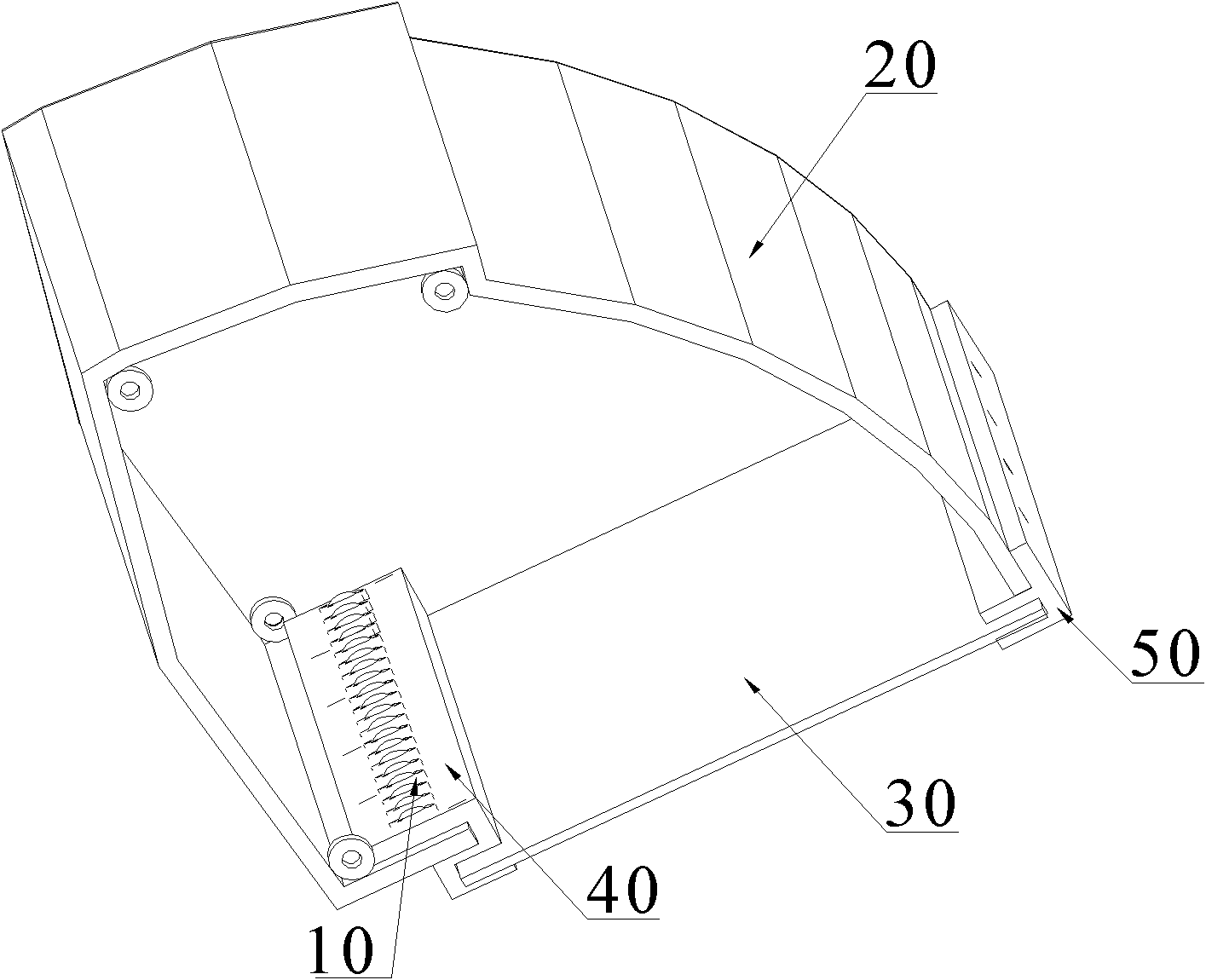
[0017] The present invention relates to an LED anti-glare lamp, which is used to reflect the light of LED 10 without directly entering human eyes, so as to play the role of anti-glare. The fixing seat 40 and the reflector 20 covering the fixing seat 40 and the LED 10 inside, the reflector 20 has a light-transmitting opening 21 so that the light emitted by the LED 10 is reflected and emitted from the light-transmitting opening 21 .

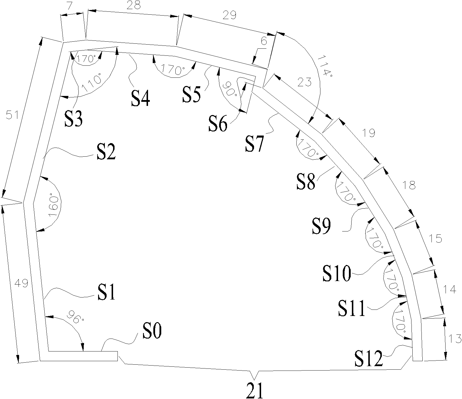
[0018] like figure 1 , figure 2 As shown, the inner surface of the reflector 20 for reflecting light has N reflective planes sequentially spliced ​​clockwise / counterclockwise, and N is an integer greater than 1. In this embodiment, N is twelve, and then twelve reflective planes These are the first reflective plane S1 to the twelfth reflective plane S12 in sequence. Twelve reflective planes are connected in turn to form an enclosing space, and there is a distance between the first reflective plane S1 at the starting end and the twelfth reflective...


PUM


Abstract

The invention relates to an LED anti-dazzle lamp which comprises a fixed base, an LED arranged on the upper surface of the fixed base and a reflecting shade that covers the fixed base and the LED, wherein the fixed base is fixed at one side near the inner surface of the reflecting shade, the inner surface of the reflecting shade comprises a plurality of reflecting planes which are sequentially spliced by included angles less than 180 degrees, and the reflecting shade has a light-transmitting port which makes reflected lights exit. All lights emitted from the LED are enclosed by the reflectingshade, therefore, the lights of the LED are certainly emitted out from the light-transmitting port after reflected by the inner surface of the reflecting shade and can not directly enter into human eyes, and therefore, the anti-dazzle aim can be achieved.

Description

technical field [0001] The present invention relates to LED lamps, more specifically, to an LED anti-glare lamp. Background technique [0002] In the design of lamps and lighting design, glare is an important reference factor. With the wide application of LED, people also need to use LED light source with long life and low energy consumption to produce anti-glare lamps. The existing LED anti-glare lamp mainly has a light-transmitting part on the LED outer cover, and the purpose of anti-glare is achieved by coating and frosting the surface of the light-transmitting part. However, the above-mentioned special treatment method for transparent parts is not only complicated in procedure and high in cost, but also has a large loss of light in the prepared transparent parts, which makes the efficiency of the whole lamp low, generally about 60%. Contents of the invention [0003] The technical problem to be solved by the present invention is to provide an LED anti-glare lamp that...

Claims


Application Information

Patent Timeline
Patent Type & Authority Applications(China)
IPC IPC(8): F21S2/00F21V17/00F21V19/00F21V7/10F21V7/04F21Y101/02
Inventor 周明杰王鑫
Owner OCEANS KING LIGHTING SCI&TECH CO LTD
Learn More