Optical coupler

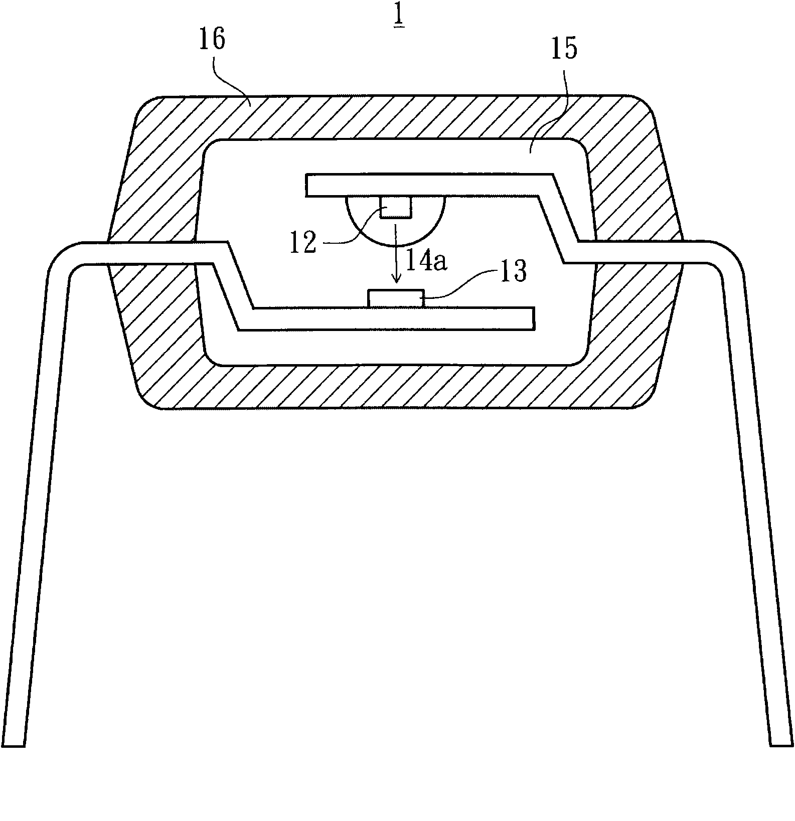
An opto-coupler and light-sensing technology, applied in the field of opto-couplers, can solve the problems of incompetent working environment, low light transmittance, large loss of light beam 14a, etc., and achieve the effect of avoiding the phenomenon of tip discharge

Inactive Publication Date: 2010-09-01
EVERLIGHT ELECTRONICS
View PDF0 Cites 5 Cited by
  • Summary
  • Abstract
  • Description
  • Claims
  • Application Information

AI Technical Summary

Problems solved by technology

Under the above-mentioned working environment, the existing optical coupler 1 will cause the light beam 14a emitted by the light-emitting chip 12 to consume too much because the light transmittance of the inner package 15 is too low, and the light-sensitive chip 13 cannot normally convert the light signal into electrical signal, but not competent for the working environment

Method used


Image

  • Optical coupler
  • Optical coupler
  • Optical coupler

Examples


Embodiment Construction

[0026] In order to have a clearer understanding of the technical features, purposes and effects of the present invention, the specific implementation manners of the present invention will now be described with reference to the accompanying drawings.

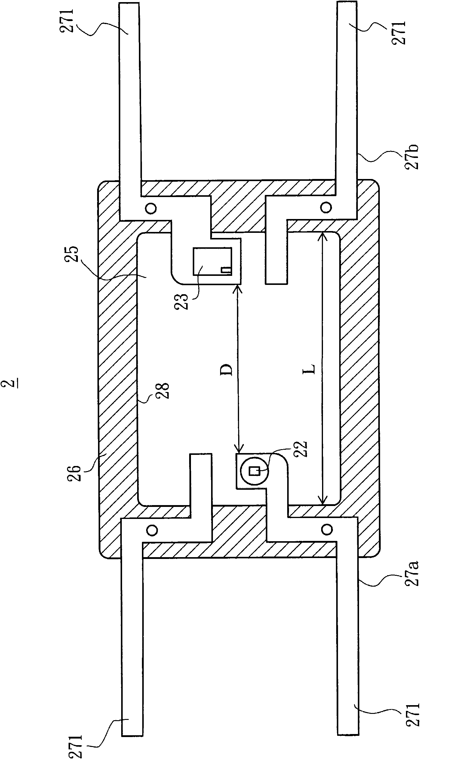
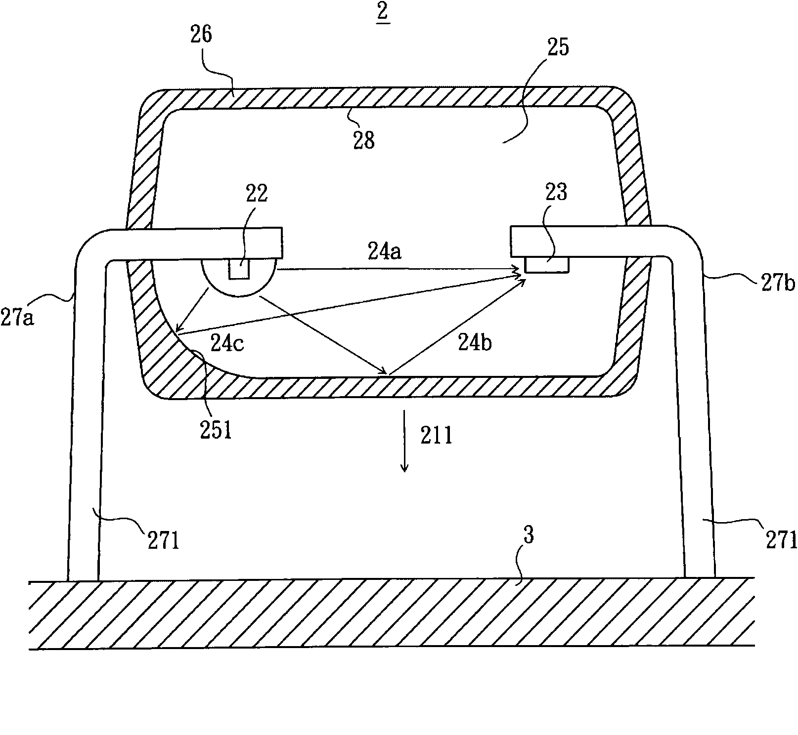
[0027] Please also see figure 2 and image 3 , the optical coupler 2 disclosed in the present invention includes a light-emitting chip 22 , a photosensitive chip 23 , a transparent inner package 25 and an outer package 26 . Wherein, the light-emitting chip 22 and the light-sensitive chip 23 are arranged on the same plane, and are also arranged toward a direction 211 of the optical coupler 2 .

[0028] After receiving an input electrical signal, the light emitting chip 22 is suitable for generating and emitting the first part 24c of the light beam, the second part 24b of the light beam and the third part 24a of the light beam, and the photosensitive chip 23 receives the first part 24c, the second part 24b and the third part 24a ...


PUM


Abstract

The invention discloses an optical coupler which comprises a luminous wafer, a light sensing wafer, a transparent internal packaging body and an external packaging body, the luminous wafer and the light sensing wafer are both arranged towards the same direction, the light sensing wafer is used for receiving a beam emitted by the luminous wafer, the transparent internal packaging body wraps the luminous wafer and the light sensing wafer, the external packaging body wraps the transparent internal packaging body, and an interface is formed between the transparent internal packaging body and the external packaging body and is used for reflecting the beam, wherein a reflection curved surface is formed on the surface of the transparent internal packaging body near the luminous wafer and used for reflecting and collecting a first part of a part of the beam to the light sensing wafer.

Description

technical field [0001] The invention relates to an optical coupler, in particular to an optical coupler with high working voltage. Background technique [0002] A photo-coupler is a circuit safety device that can convert electricity into light and light into electricity through the mutual matching of a light-emitting chip and a light-sensitive chip. In this way, the optocoupler can avoid situations such as surges and instability of the electrical signal at the source end due to the direct electrical connection only using the circuit, causing the circuit at the receiving end to burn out or fail to operate normally. [0003] Such as figure 1 As shown, the conventional optical coupler 1 includes a light-emitting chip 12 and a light-sensitive chip 13 facing each other up and down. The light-emitting chip 12 and the light-sensitive chip 13 are covered by an inner package body 15 , and the inner package body 15 is an insulating layer, which prevents conduction between the light-...

Claims


Application Information

Patent Timeline
Patent Type & Authority Applications(China)
IPC IPC(8): H01L25/16H01L31/06H01L33/00
Inventor 苏炤亘赖律名陈盈仲
Owner EVERLIGHT ELECTRONICS
Why Eureka
Try Eureka