
Electric motor for compressor, compressor, and freezing cycle device

A technology for compressors and motors, which is applied in the field of compressors, refrigeration cycle devices, and motors for compressors. It can solve the problems of high component prices, unrealizable stator cores, and reduced efficiency of single-phase induction motors, etc., to increase the starting speed. Moment, the effect of suppressing the rise in component prices

Inactive Publication Date: 2010-09-01
MITSUBISHI ELECTRIC CORP
View PDF1 Cites 3 Cited by
  • Summary
  • Abstract
  • Description
  • Claims
  • Application Information

AI Technical Summary

Problems solved by technology

[0007] However, as in the above-mentioned Patent Document 1, since the method of adding a capacitor for starting requires a switch for opening and closing the capacitor for starting, there is a problem that the cost of parts becomes higher.
[0008] In addition, the method of shifting the phase difference between the main winding and the auxiliary winding by 90° (electrical angle) has the problem that it cannot be realized due to the number of slots of the stator core.
[0009] In addition, the method of increasing the secondary resistance of the rotor to increase the starting torque has the problem of lowering the efficiency during operation of the single-phase induction motor.

Method used


Image

  • Electric motor for compressor, compressor, and freezing cycle device
  • Electric motor for compressor, compressor, and freezing cycle device
  • Electric motor for compressor, compressor, and freezing cycle device

Examples


Embodiment approach 1

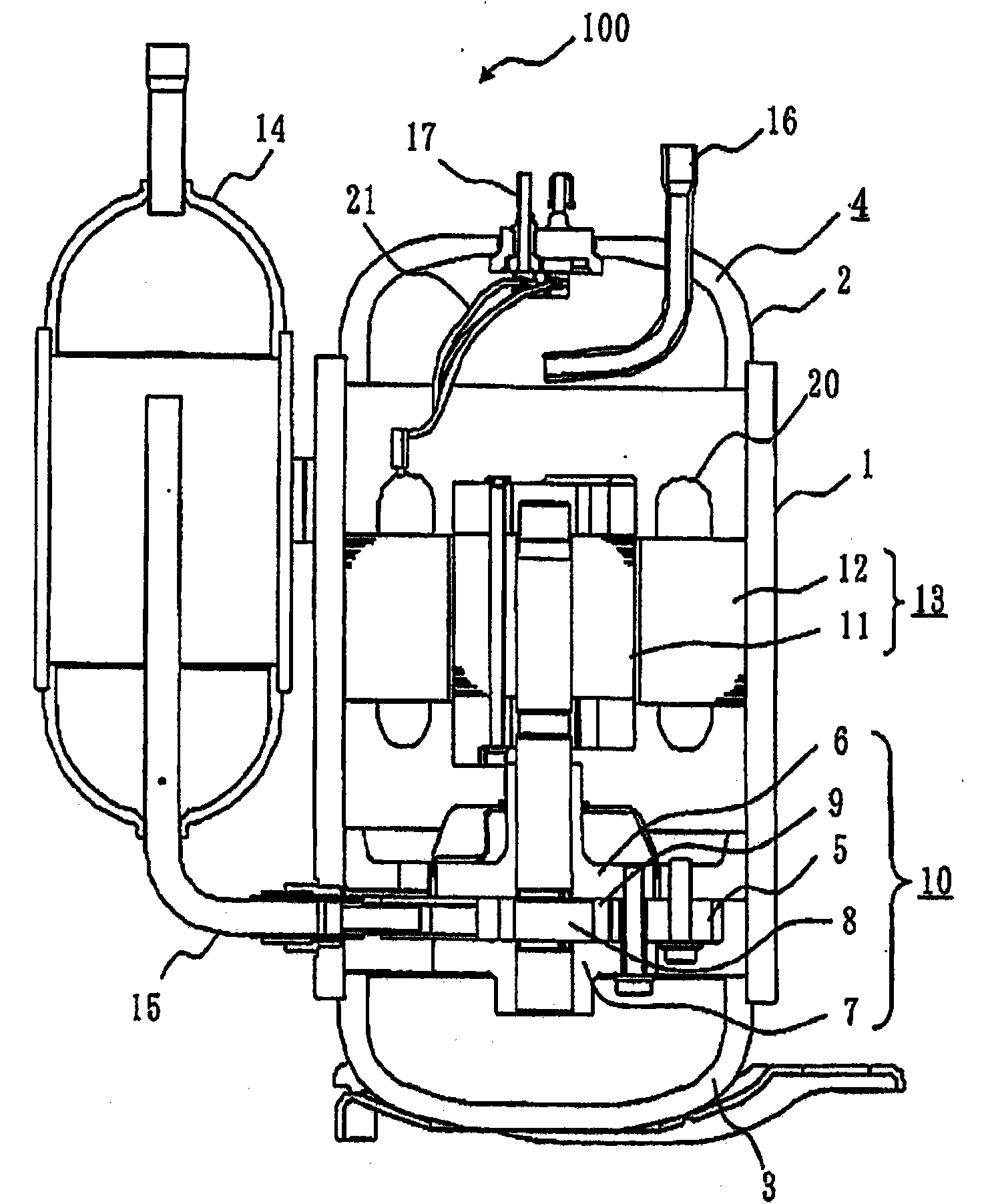
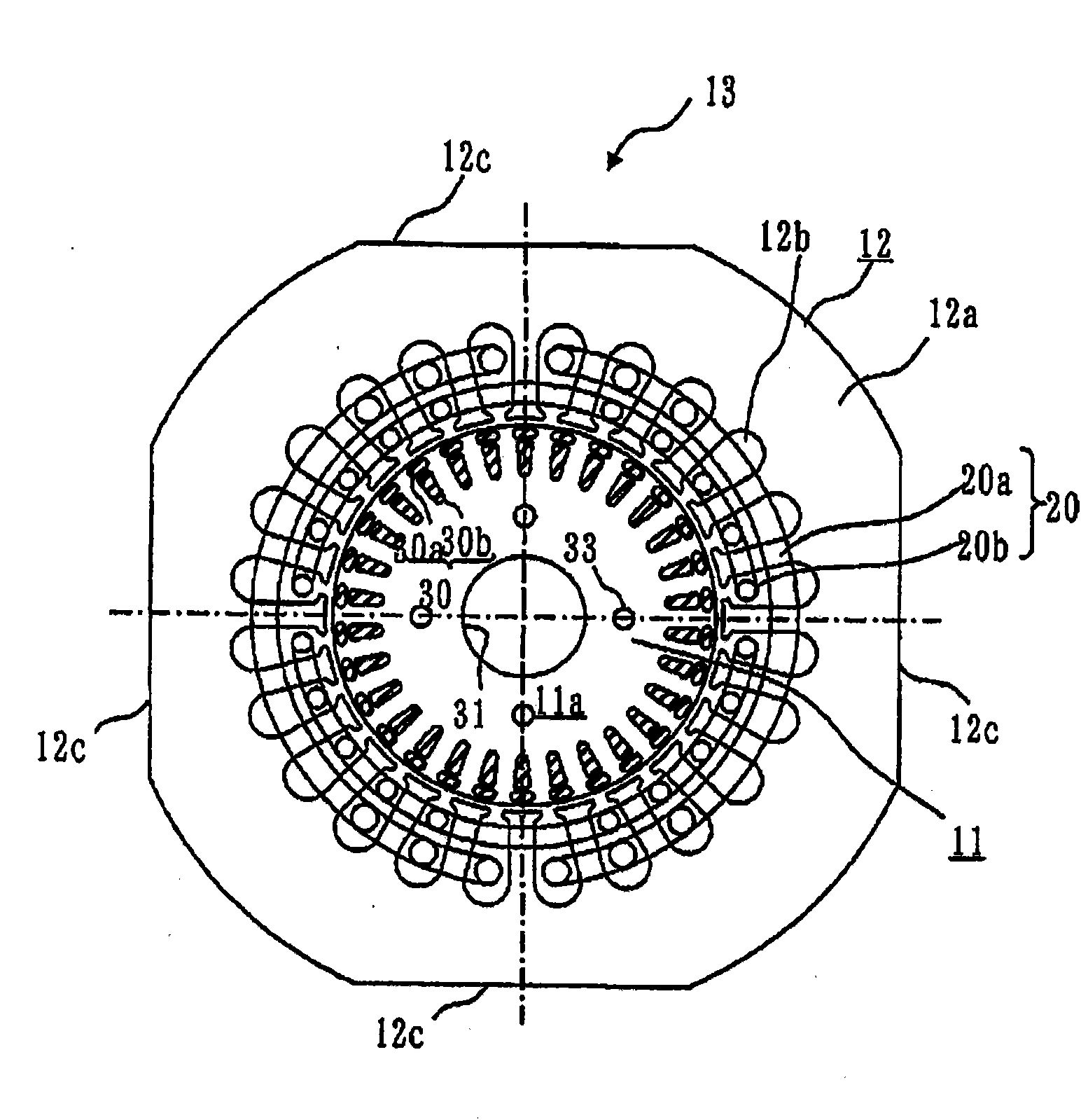
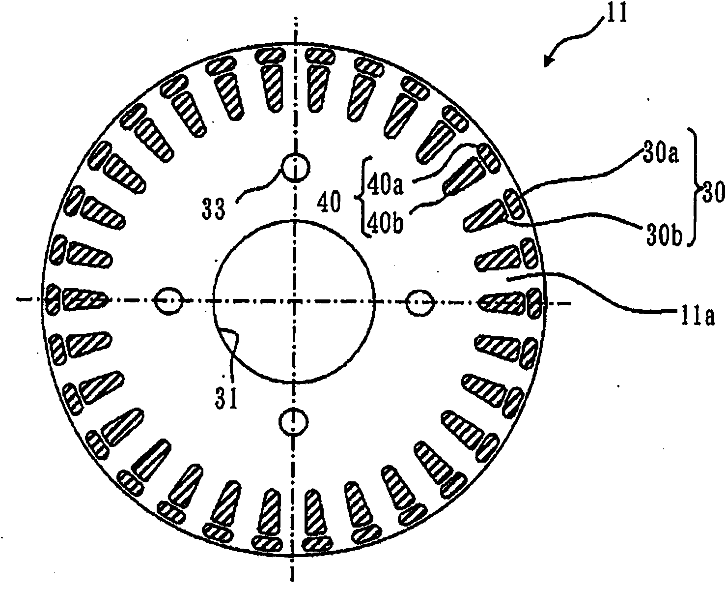
[0100] Figure 1 to Figure 14 is a diagram showing Embodiment 1, figure 1 is a longitudinal sectional view of the rotary compressor 100, figure 2 is a transverse sectional view showing the electric element 13, image 3 is a transverse cross-sectional view showing the rotor 11 of the electric element 13, Figure 4 is a perspective view showing the rotor 11 of the electric element 13, Figure 5 is a side view of the rotor 11 provided with a cutout 34 on the end ring 32, Image 6 is a side view of the rotor 11 provided with end ring ventilation holes 32a, Figure 7 It is a transverse cross-sectional view of the vicinity of the electric element 13 showing an example in which ventilation holes are provided on the stator 12 side, Figure 8 , Figure 9 is a transverse sectional view of the groove of the rotor 11, Figure 10 is a graph showing the relationship between the volume ratio of the end ring 32 and the rotor core 11a, the secondary resistance R2, and the motor efficie...


PUM


Abstract

An object is to provide an electric motor for a compressor starting torque for which can be increased with the rise of the price of a component and a deterioration in efficiency in operation suppressed. The electric motor for the compressor is housed with a compressor element for compressing a cooling medium in an airtight container and connected to the compressor element via a driving axis to drive the compressor element. The electric motor for the compressor comprises a stator fixed to the inner periphery portion of the airtight container, a rotator (11) which is arranged on the inner side of the stator and which has a rotator core (11a), and a double squirrel-cage conductor which is cast in the rotator core (11a) and which is constituted by a secondary conductor comprising an outer layer secondary conductor and an inner layer secondary conductor and an end ring (32). In the rotator core (11a), an air hole (33) which is the passage of the cooling medium is provided. The inner diameter side of the end ring (32) is enlarged to a driving axis side in such a manner that the air hole (33) is sealed. The end ring (32) has a cutting (34) for allowing the air hole (33) to be communicated with the space of the airtight container so as not to seal the air hole (33).

Description

technical field [0001] The present invention relates to a motor for a compressor, a compressor and a refrigeration cycle device. Background technique [0002] In a compressor used in a refrigerating and air-conditioning apparatus such as an air conditioner, a brushless DC motor, an induction motor, or the like is used as a motor that drives a compression mechanism. Among the induction motors, an ordinary cage type induction motor (single cage type) is mainly used. [0003] Induction motors include three-phase induction motors and single-phase induction motors. When an induction motor is used for a compressor, since the starting torque of a three-phase induction motor is large, there are few problems related to starting. However, in single-phase induction motors, sufficient starting torque cannot be obtained only with an externally connected operation capacitor. Therefore, a capacitor for starting may be added in addition to a capacitor for operation (for example, refer to...

Claims


Application Information

Patent Timeline
Patent Type & Authority Applications(China)
IPC IPC(8): H02K1/32H02K7/14H02K17/18
CPCH02K17/18H02K1/32
Inventor 堤贵弘及川智明风间修田岛庸贺奥川贞美吉野勇人矢部浩二
Owner MITSUBISHI ELECTRIC CORP
Learn More