

Adjustable mid-face bone tractor and design method thereof
A technology of bone distractor and design method, applied in the field of medical equipment
- Summary
- Abstract
- Description
- Claims
- Application Information
AI Technical Summary
Problems solved by technology
Method used
Image

Examples
Embodiment 1
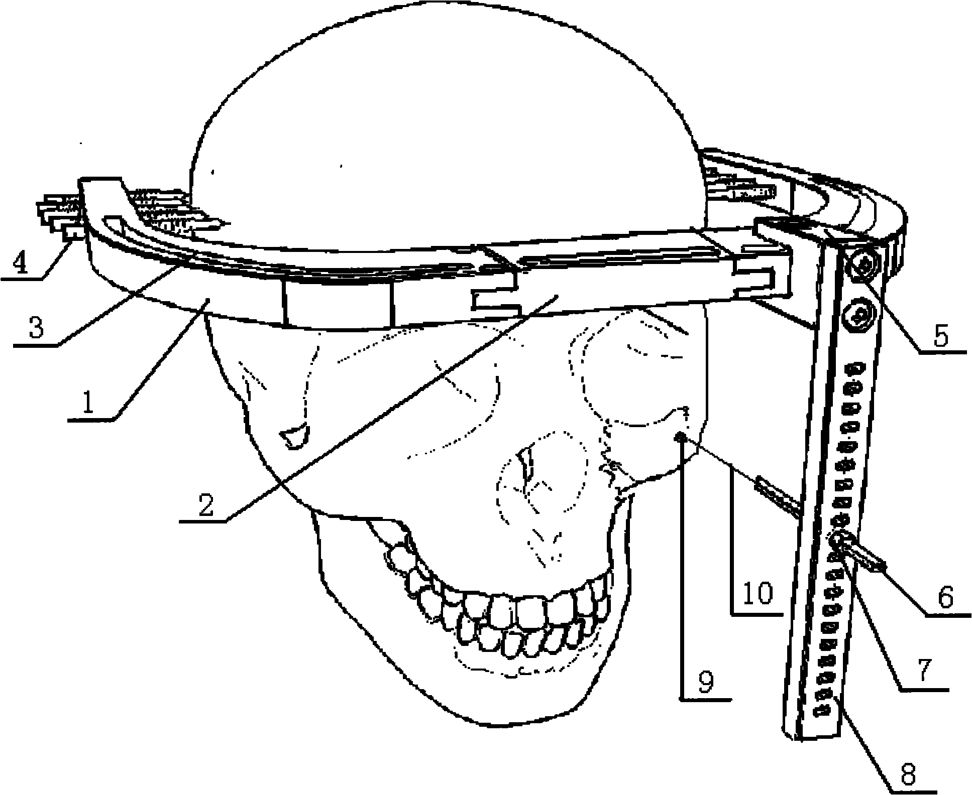
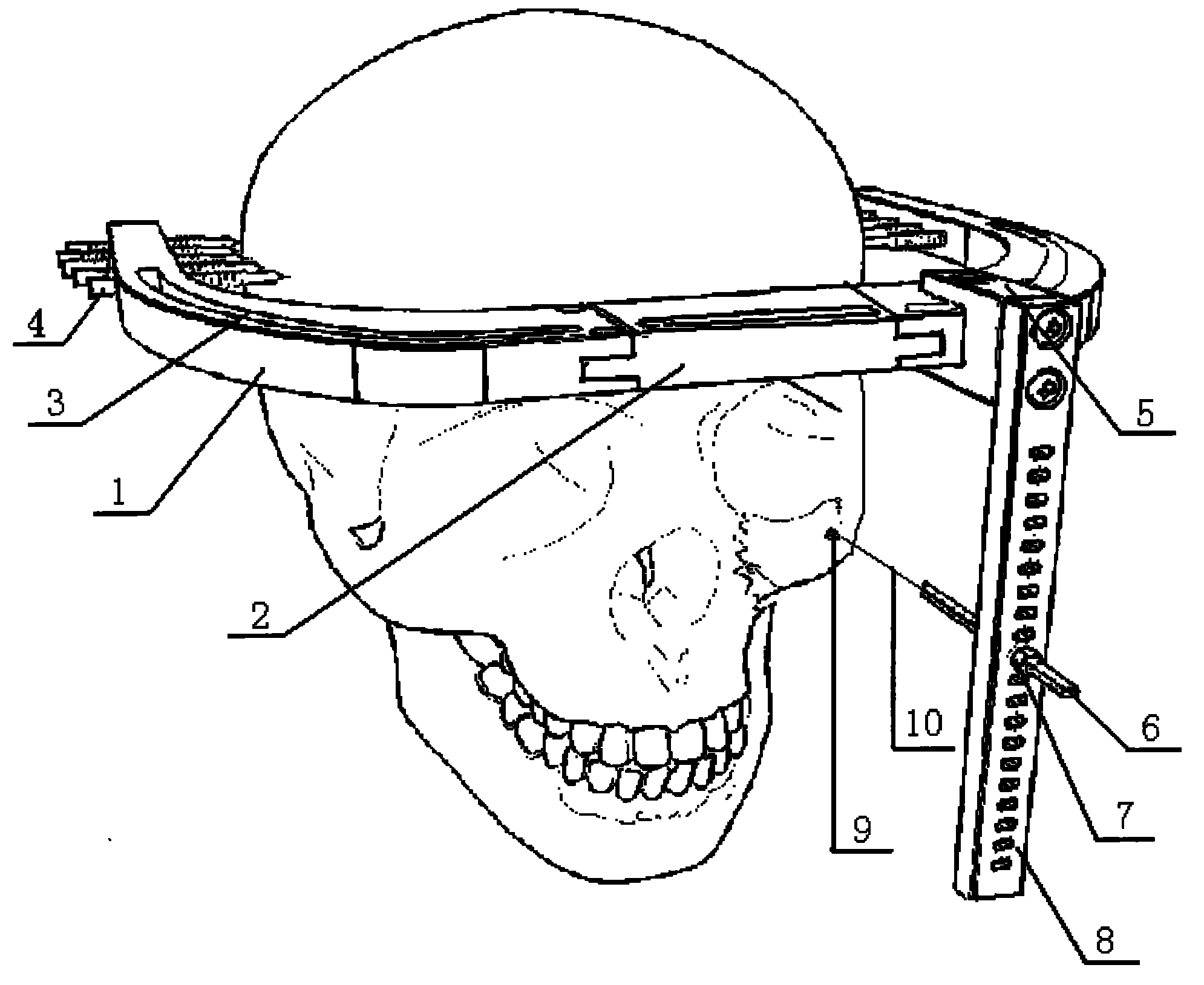
[0016] Embodiment 1: as figure 1 As shown, an adjustable mid-face bone retractor at least includes a bracket, a skull fixation nail 4, a titanium traction nail 9, and a traction wire 10. 1 is composed of fixedly connected adjustable connecting rods through detachable connectors; the middle part of arc-shaped connecting frame 1 is fixedly connected with bracket connecting block 2 through detachable connecting parts; arc-shaped connecting frame 1 can fix one or more adjustable connecting rods according to needs Rod, the adjustable connecting rod is connected with traction screw 6 and traction nut 7. The adjustable connecting rod is composed of a vertical connecting block 5 and a vertical connecting rod 8 vertically fixedly connected, and the vertical connecting rod connecting block 5 is fixedly connected at any position on the draw-in groove 3 of the arc-shaped connecting frame 1 . A plurality of traction screws 6 are connected to the vertical connecting rod 8, facing different...
Embodiment 2
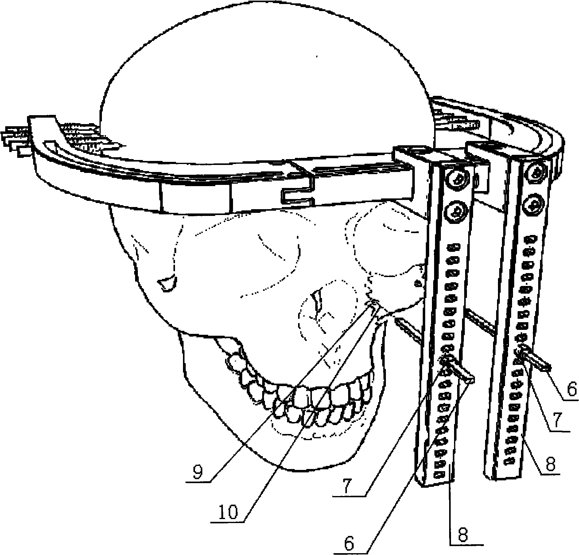
[0018] Embodiment 2: as figure 2 As shown, the left maxillary fragment of the patient is to be pulled forward and lateral, and rotated laterally. The implementation method is basically the same as that of Embodiment 1, the difference is that two adjustable connecting rods are fixed on the arc-shaped connecting frame 1, that is, the original adjustable connecting rod on the right side of the arc-shaped connecting frame 1 is placed adjacent to the left side. An adjustable connecting rod is fixed, and one end of a traction titanium nail 9 can be fixed on the outer surface of the patient's left maxillary segment, and the other end of the traction titanium nail 9 is connected to the traction screw on the vertical connecting rod 8 from the intermaxillary through the traction wire 10 6. The maxillary segment can be drawn outward by first rotating the traction nut 7 clockwise; one end of the second traction titanium nail is fixed on the end of the patient's left maxillary segment clo...
PUM
 Abstract
Description
Claims
Application Information