Flash-type brake lamp controller with fault warning function

A fault alarm and brake light technology, applied in optical signals, vehicle components, sound signal devices, etc., can solve problems such as damage warning function, untrue details, and reduced circuit reliability

Inactive Publication Date: 2013-12-04
FUJIAN NORMAL UNIV
View PDF16 Cites 1 Cited by
  • Summary
  • Abstract
  • Description
  • Claims
  • Application Information

AI Technical Summary

Problems solved by technology

The disadvantage is that it is not convenient to install the light-emitting diodes described in the document on the finalized car, and it does not include the brake light damage warning function; by the way, it is pointed out that the details of the technical solution published in the patent document are not true, such as IC (that is, 555 time base circuit) The pin number is incorrect, and the freewheeling diode is not connected to both ends of the relay coil
[0009] The Chinese patent application number is 200520112630.4, which discloses an intelligent car brake light changing device, which can effectively distinguish between normal braking and emergency braking. During emergency braking, the brake light is flashing, and the emergency braking signal is from the anti-lock braking system circuit. Extracted, the disadvantage is that more components are used, even up to three IC integrated circuits, which reduces the reliability of the circuit, and the device does not include a brake light damage warning function
However, the brake light should not flash continuously for a long time, otherwise it will easily cause visual fatigue to the driver behind. Therefore, it is advisable to use the method that the brake light changes from a short flash to a constant light after the brake pedal is stepped on until the brake light is off after the brake pedal is released. Frequent switching is easy to damage the filament, so the brake light failure alarm function to remind the driver to replace the bulb is extremely important for safe driving

Method used


Image

  • Flash-type brake lamp controller with fault warning function
  • Flash-type brake lamp controller with fault warning function
  • Flash-type brake lamp controller with fault warning function

Examples


Embodiment Construction

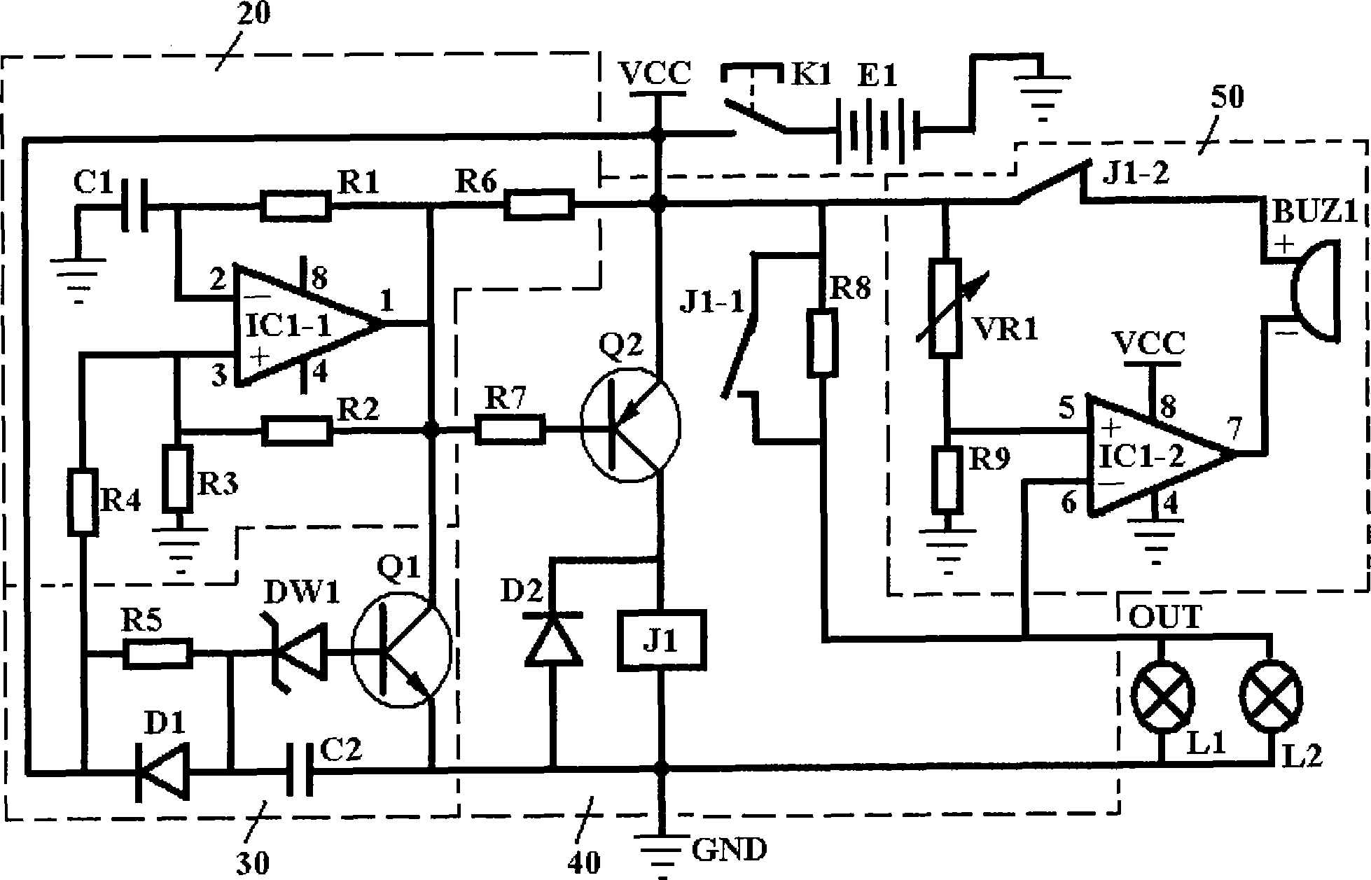
[0047] Attached below figure 2 Further description is implemented to the technical scheme of the present invention:

[0048] The circuit structure composition and specific device connection methods are as the technical solution described in the summary of the invention, and will not be described here. A set of optional device models or device main parameters are listed below, assuming that the parameters of the brake light bulb are the standard 12V / 20W.

[0049] Voltage comparison integrated chip IC1: LM393 is selected. This chip contains two sets of voltage comparison amplifiers, which can work with a single power supply. The voltage range of the single power supply is 1V to 18V, which completely covers the normal working voltage of the car battery. Use this chip for circuit connection The pin numbers are exactly attached with figure 2 The pin number of IC1 in;

[0050] Relay J1: Choose a relay that includes a normally open contact, a normally closed contact and a moving ...


PUM


Abstract

The invention relates to a brake lamp controller with flash function and fault warning function. The brake lamp controller is characterized in that a brake lamp controller circuit consists of four functional modules comprising a timing circuit, an oscillating circuit, a drive circuit and an audio warning circuit, wherein the timing circuit is connected to the oscillating circuit through an NPN-type triode Q1; the oscillating circuit is connected to the drive circuit through a PNP-type triode Q2; the drive circuit is connected to the audio warning circuit by using a partial voltage tap and a normally-closed switch of a relay; and three connecting wires are connected outside the brake lamp controller. The working power supply of the controller directly adopts a primary power supply of a motor vehicle. After a brake pedal is treaded down, a brake lamp first flashes and then is normally on so as to effectively remind a back driver. The controller also has the function of warning poor brake lamp contact or filament open-circuit damage; a few of external connecting wires are convenient for mounting or refitting; no static power consumption is favorable for saving energy and prolonging the service life of a storage battery of the motor vehicle; the power supply voltage has wide applicable range; and a pure simulation mode easily ensures the working reliability of the circuit.

Description

technical field [0001] The invention relates to a brake light controller for motor vehicles, in particular to a brake light controller with flashing function and fault warning function. Background technique [0002] Car rear-end collision is a high traffic accident, so brake lights are especially important for the warning effect of the rear car. The warning effect of brake lights includes warning effect (or efficiency) and the driver's timely knowledge of two aspects of the failure of the car's brake lights. Prior patents have proposed some solutions for this. [0003] The Chinese patent application number is 200810246729.1, which discloses a vehicle taillight control device consisting of a vehicle speed sensor, a radar principle rangefinder and a controller comprising circuits such as a single-chip microcomputer. The device can predict the safe vehicle distance according to the actual vehicle speed and vehicle distance of the two front and rear vehicles and drive the tail ...

Claims


Application Information

Patent Timeline
Patent Type & Authority Patents(China)
IPC IPC(8): B60Q1/44B60Q1/46B60Q5/00
Inventor 廖晓东洪亲蔡坚勇陈由甲张亮
Owner FUJIAN NORMAL UNIV
Why Eureka
Try Eureka