Electronic rearview mirror system and vehicle

An electronic rearview mirror and video image technology, which is applied in the direction of closed-circuit television systems, televisions, electrical components, etc., can solve the problems that the irradiation range of the five-category mirror cannot be met, the vehicle cannot meet the installation requirements, and the irradiation range cannot be covered. Large-scale commercial production and use, avoiding misjudgment and dizziness, and avoiding the effects of visual fatigue

Active Publication Date: 2020-04-17
SHANGHAI YUXING ELECTRONICS TECH CO LTD
View PDF5 Cites 7 Cited by
  • Summary
  • Abstract
  • Description
  • Claims
  • Application Information

AI Technical Summary

Problems solved by technology

However, this electronic rearview mirror system can only observe the rearward field of view on one side of the vehicle. Since the irradiation range of the camera cannot cover the front of the vehicle, it cannot meet the national standard six-category mirror installation requirements, and it cannot meet the five-category mirror for trucks. In addition, a separate set of monitors is required to display the video of the field of view directly in front of the vehicle.
[0010] Based on the above problems, how to make the electronic rearview mirror system realize that multiple cameras correspond to one display screen, so as to meet the needs of the driver to observe and judge multiple viewing angles in real time, accurately and quickly, and at the same time solve the problems caused by changes in the driving state of the vehicle. The image display distortion is a technical difficulty that the industry needs to solve urgently

Method used


Image

  • Electronic rearview mirror system and vehicle
  • Electronic rearview mirror system and vehicle
  • Electronic rearview mirror system and vehicle

Examples


Embodiment 1

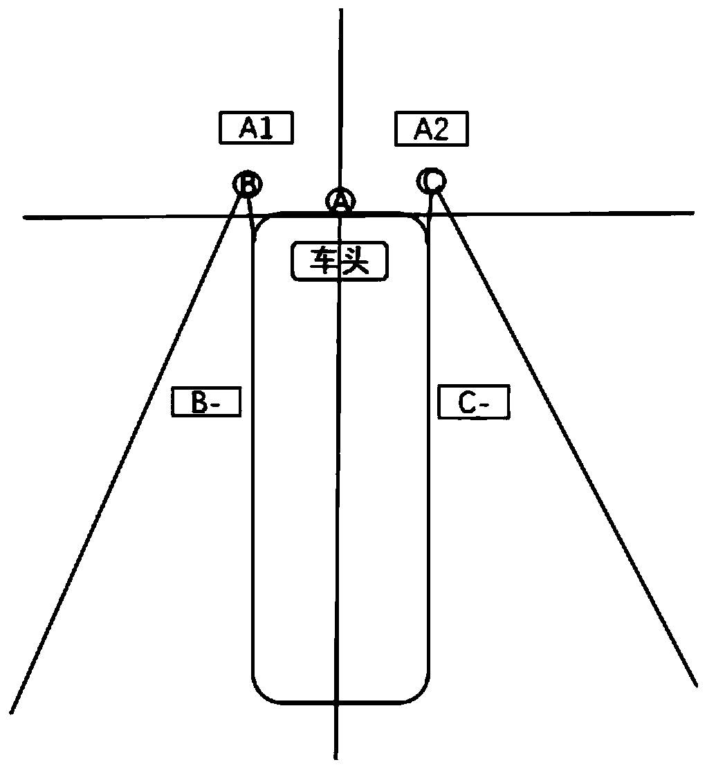
[0072] The first embodiment proposes an electronic rearview mirror system, such as figure 2 As shown, the camera 170 of the electronic rearview mirror system includes at least three cameras, and the three cameras are specifically: a front camera A, a left rear camera B, and a right rear camera C. Among them, the front camera A is limited to the center axis of the vehicle and is installed in the middle of the vehicle or on the top of the vehicle. The lens of the front camera A adopts a wide-angle camera with a horizontal shooting angle of 90-150 degrees, and the optical axis of the front camera A Tilt down 20-50 degrees, and the front camera A illuminates the ground. The illuminated area includes two parts, which are defined as the A1 area and the A2 area. The left rear camera B and the right rear camera C are respectively installed on the left and right sides of the front of the vehicle. Both lenses are wide-angle cameras with a horizontal shooting angle of 90-150 degrees, and ...

Embodiment 2

[0083] The second embodiment proposes an electronic rearview mirror system, such as Figure 5 As shown, the camera 170 of the electronic rearview mirror system includes at least 5 cameras, and the 5 cameras are specifically: front camera A, lower left camera B, lower right camera C, left rear camera D, and right rear camera E. Among them, the front camera A is limited to the center axis of the vehicle and is installed in the middle of the vehicle or on the top of the vehicle. The lens of the front camera A adopts a wide-angle camera with a horizontal shooting angle of 90-150 degrees, and the optical axis of the front camera A Tilt down 20-50 degrees, and the front camera A illuminates the ground. The illuminated area includes two parts, which are defined as the A1 area and the A2 area. The lower left camera B and the lower right camera C are respectively installed on the left and right sides of the front of the vehicle. The images taken by the two are taken at the intersection o...


PUM


Abstract

The invention discloses an electronic rearview mirror system and a vehicle. The electronic rearview mirror system comprises a plurality of cameras, a display screen and an image integration processingmodule. The image integrated processing module comprises an image acquisition module, an image processing module and an image display module; the image processing module selects to-be-displayed imagedata based on the image data acquired by the image acquisition module and an actual vehicle signal, recombines the to-be-displayed images and splices the to-be-displayed images to form a whole-screensingle-picture image, or cuts the to-be-displayed images into a plurality of continuously arranged sub-images in the transverse direction or the radial direction according to a preset proportion. According to the invention, images obtained by the plurality of cameras are spliced or segmented and thus the plurality of cameras correspond to one display picture; the driver can accurately and quicklyobserve and judge the visual fields of multiple visual angles in real time, and change and display of a display picture along with the running state condition of the vehicle are realized through control, so that distortion of image display is avoided, and the running safety is greatly improved.

Description

Technical field [0001] The present invention relates to the technical field of electronic rear-view mirror systems for vehicles, in particular to an electronic rear-view mirror system and a vehicle including the electronic rear-view mirror system. Background technique [0002] At present, most vehicles use mercury glass as the vehicle's indirect vision reflector. Due to the angular relationship between the driver's eye point observation and the reflection of the traditional physical rearview mirror, the observation range is small, which brings blind spots to the driver's vision, which seriously affects driving safety, especially No light at night, rain and snow weather have a greater impact on vision. [0003] With the continuous development of camera technology, electronic rearview mirrors have gradually replaced traditional physical rearview mirrors on the market. Multi-generation electronic rear-view mirrors take advantage of the camera's field of view, night vision, and its ow...

Claims


Application Information

Patent Timeline
Patent Type & Authority Applications(China)
IPC IPC(8): B60R1/00H04N7/18
CPCB60R1/00H04N7/181B60R2300/105B60R2300/8046
Inventor 刘拾玉付绍航
Owner SHANGHAI YUXING ELECTRONICS TECH CO LTD
Why Eureka
Try Eureka