

Malfunction detection method of incremental encoder
An incremental encoder and fault detection technology, which is applied in the direction of instruments, can solve the problems of non-broken fault detection of incremental encoders, achieve accurate detection, and realize the effect of simple circuit
Inactive Publication Date: 2010-09-08
HARBIN INST OF TECH
View PDF0 Cites 39 Cited by
- Summary
- Abstract
- Description
- Claims
- Application Information
AI Technical Summary
Problems solved by technology
The purpose of the present invention is to provide a fault detection method for incremental encoders, which solves the problem that the prior art cannot detect non-broken wire faults of incremental encoders
Method used
View moreImage
Smart ImageViewing Examples

Examples
specific Embodiment approach 1
specific Embodiment approach 2
specific Embodiment approach 3
Login to View More PUM
 Abstract
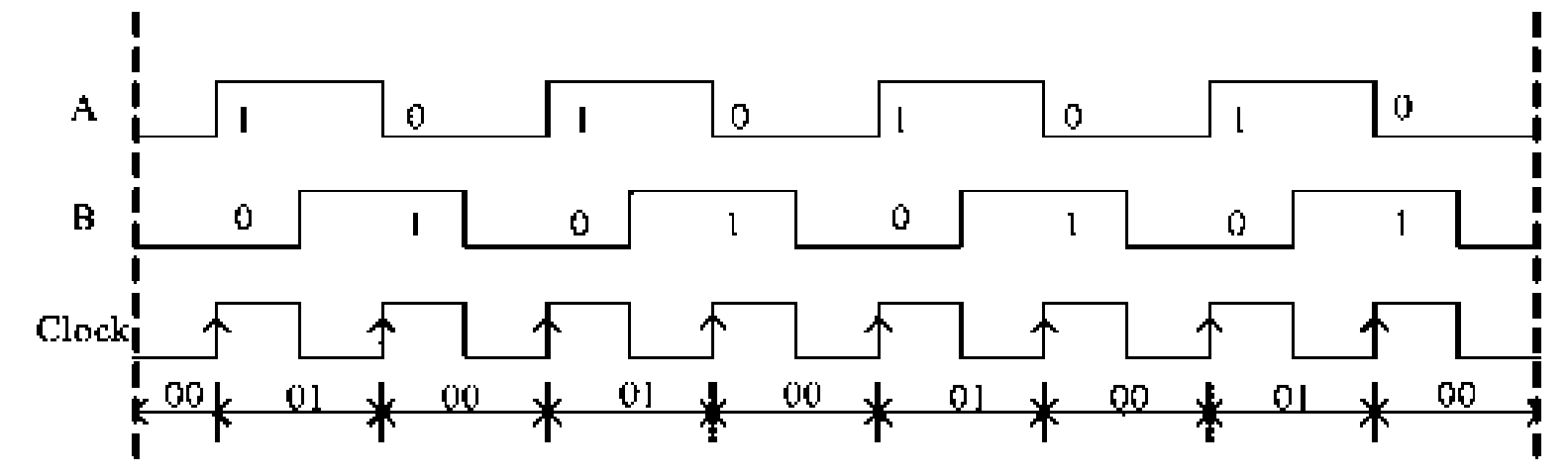
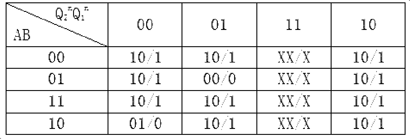
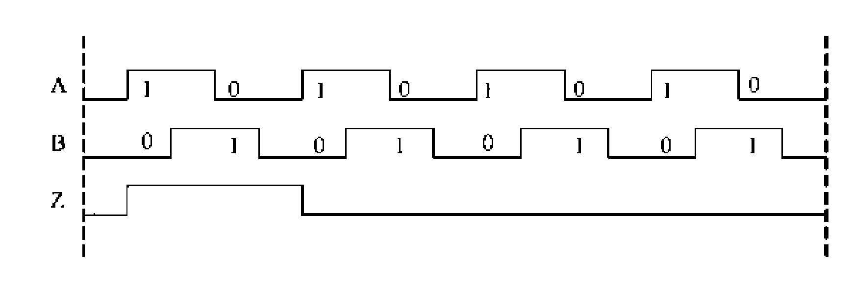
The invention relates to a malfunction detection method of an incremental encoder, which belongs to the malfunction detection field of the encoder, and solves the problems of the prior art that the non-wire-break malfunction of the incremental encoder cannot be detected. An electric pulse signal A and an electric pulse signal B of the incremental encoder, phase difference of which is 90 degrees, are exclusive or to obtain a synchronic clock signal Clock, circuit output states Q2 and Q1 of two JK triggers FF2 and FF1 which are triggered by two rising edges are determined according to the state of the electric pulse signals A and B at the rising edge time of every two adjacent periods of the Clock, and the malfunction of the incremental encoder is judged according to the output state Q2 and Q1. The method also comprises the detection of a Z pulse signal of the incremental encoder: a Z pulse signal is adopted to preset a cascaded counter so as to count the pulse number which is outputted by the synchronic clock signal Clock when incremental encoder rotates a circle, and the malfunction of the Z pulse signal is judged according to the overflow of the cascaded counter. The method is applicable to the malfunction detection of the incremental encoder.
Description
Fault Detection Method of Incremental Encoder technical field The invention relates to a fault detection method of an incremental encoder, which belongs to the field of fault detection of encoders. Background technique Currently commonly used encoders include incremental encoders and absolute encoders. Incremental encoders have a much wider range of applications than absolute encoders due to their low cost. The photoelectric code disc of the incremental encoder is made of a glass disc coated with a layer of opaque metal film, and then made of circumferentially equidistant light-transmitting and opaque stripes on the metal film. When the code disc rotates, light passes through the transparent stripes, and no light passes through the opaque stripes. The resulting light and dark signals are received by the photosensitive element, and then converted into electrical pulse signals for output. The code disc of the incremental encoder is usually engraved with two code tracks, eac...
Claims
Login to View More Application Information
Patent Timeline
 Patent Type & AuthorityApplications(China)
IPC IPC(8): G01D18/00
Inventor于泳徐冰徐殿国杨荣峰王高林丛培城
OwnerHARBIN INST OF TECH