Gas-insulated circuit breaker

一种气体绝缘、断路器的技术,应用在高压空气断路器、电路、电气元件等方向,能够解决调整作业及组装作业花费时间、制造成本高等问题,达到实现紧凑化及低成本化、制造成本低价、避免高电场的发生的效果

Inactive Publication Date: 2010-09-08
KK TOSHIBA
View PDF8 Cites 7 Cited by
  • Summary
  • Abstract
  • Description
  • Claims
  • Application Information

AI Technical Summary

Problems solved by technology

Therefore, the number of components of the gas flow path adjustment mechanism increases, and each part is interlocked. Therefore, it takes time to adjust and assemble the interlocking parts to operate smoothly.
That is, there is a disadvantage that the manufacturing cost is high for components that suppress the gas flow rate from the insulating nozzle

Method used


Image

  • Gas-insulated circuit breaker
  • Gas-insulated circuit breaker
  • Gas-insulated circuit breaker

Examples


no. 2 Embodiment approach

[0101] (constitute)

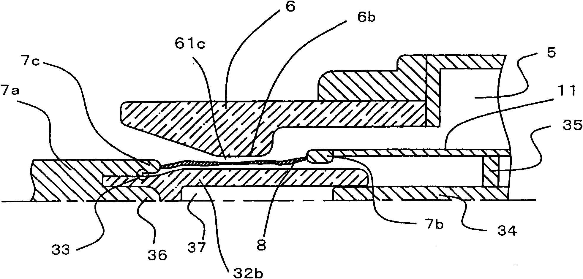
[0102] Next, use image 3 A second embodiment of the present invention will be specifically described. image 3 It shows the state near the arc during the breaking operation of the gas insulated circuit breaker. Since each component has a rotationally symmetrical shape, only the upper half of the center line is drawn.

[0103] The basic configuration of the second embodiment is the same as that of the first embodiment, but is characterized by the following points. That is, if image 3 As shown in the figure, an electric field relaxation shield 36 is provided at the center of the front end portion of the fixed arc contact 7a. The electric field relaxation shield 36 is embedded in the inner-nozzle insulating member 32b. In addition, reference numeral 35 is a rod support mounted on the hollow rod 11 .

[0104] The inner nozzle insulating member 32b of the second embodiment has a hollow structure in which a hole 37 is formed, and a guide rod 34 fixed to ...

no. 3 Embodiment approach

[0120] (constitute)

[0121] Next, use Figure 4 A third embodiment of the present invention will be described. Figure 4 It shows the state near the arc during the breaking operation of the gas insulated circuit breaker. Since each component has a shape symmetrical to the rotation axis, only the upper half of the center line is drawn.

[0122] The characteristic configuration of the third embodiment resides in the point of including the nozzle inner insulating member 32 c having the tapered surface 38 . The tapered surface 38 is formed by drawing a curve such that the diameter near the center of the nozzle inner insulating member 32c is large, and the diameter becomes smaller toward the vicinity of the ends.

[0123] That is, the diameter of the inner nozzle insulating member 32c formed with the tapered surface 38 becomes uneven along the axial direction. Therefore, the size of the gas flow path 61c of the insulating nozzle 6 according to the third embodiment changes with ...


PUM


Abstract

The object of the present invention is to provide a gas-insulated circuit breaker that can contribute to extending product life and reducing impact on the environment, lead to downsizing and lower costs, and achieve high opening performance and high reliability. In an insulating nozzle (6), a cylindrical inside-nozzle insulating member (32a) is provided coaxially with the insulating nozzle (6). The inside-nozzle insulating member (32a) is firmly bonded to the end face of the front end section, while one side in the fixed arcing contact (7a), which is opposite with a movable arcing contact (7b) is used as the front side.

Description

technical field [0001] The present invention relates to a gas insulated circuit breaker of a puffer type which ejects an insulating gas to extinguish an arc, and particularly relates to a gas insulated circuit breaker which improves the configuration of an insulating nozzle for injecting insulating gas. Background technique [0002] A gas insulated circuit breaker is a device that arranges a pair of contacts in a closed container filled with insulating gas, and is often used as an on-off switch for current in power transmission and distribution systems. Below, refer to Image 6 and Figure 7 A conventional example of a puffer type gas insulated circuit breaker will be specifically described. [0003] Image 6 is a cross-sectional view of a compressed gas-insulated circuit breaker, Figure 7 These are enlarged cross-sectional views of the vicinity of the arc 8, and both show the state of the breaking operation. The components of the gas insulated circuit breakers shown in ...

Claims


Application Information

Patent Timeline
Patent Type & Authority Applications(China)
IPC IPC(8): H01H33/91
CPCH01H2033/566H01H33/7076H01H2033/888H01H33/703H01H33/901H01H33/905
Inventor 内井敏之森正新海健
Owner KK TOSHIBA
Why Eureka
Try Eureka