Device for the production of fancy yarn

A technology of colored threads and yarns, applied in the direction of textiles, papermaking, yarns, etc.

Active Publication Date: 2010-09-08
SSM萨罗瑞士麦特雷有限公司
View PDF11 Cites 6 Cited by
  • Summary
  • Abstract
  • Description
  • Claims
  • Application Information

AI Technical Summary

Problems solved by technology

Presetting of a certain deflection length can therefore only be carried out conditionally, so that weft stripe effects can occur in fabrics woven from fancy threads produced with this device

Method used


Image

  • Device for the production of fancy yarn
  • Device for the production of fancy yarn
  • Device for the production of fancy yarn

Examples


Embodiment Construction

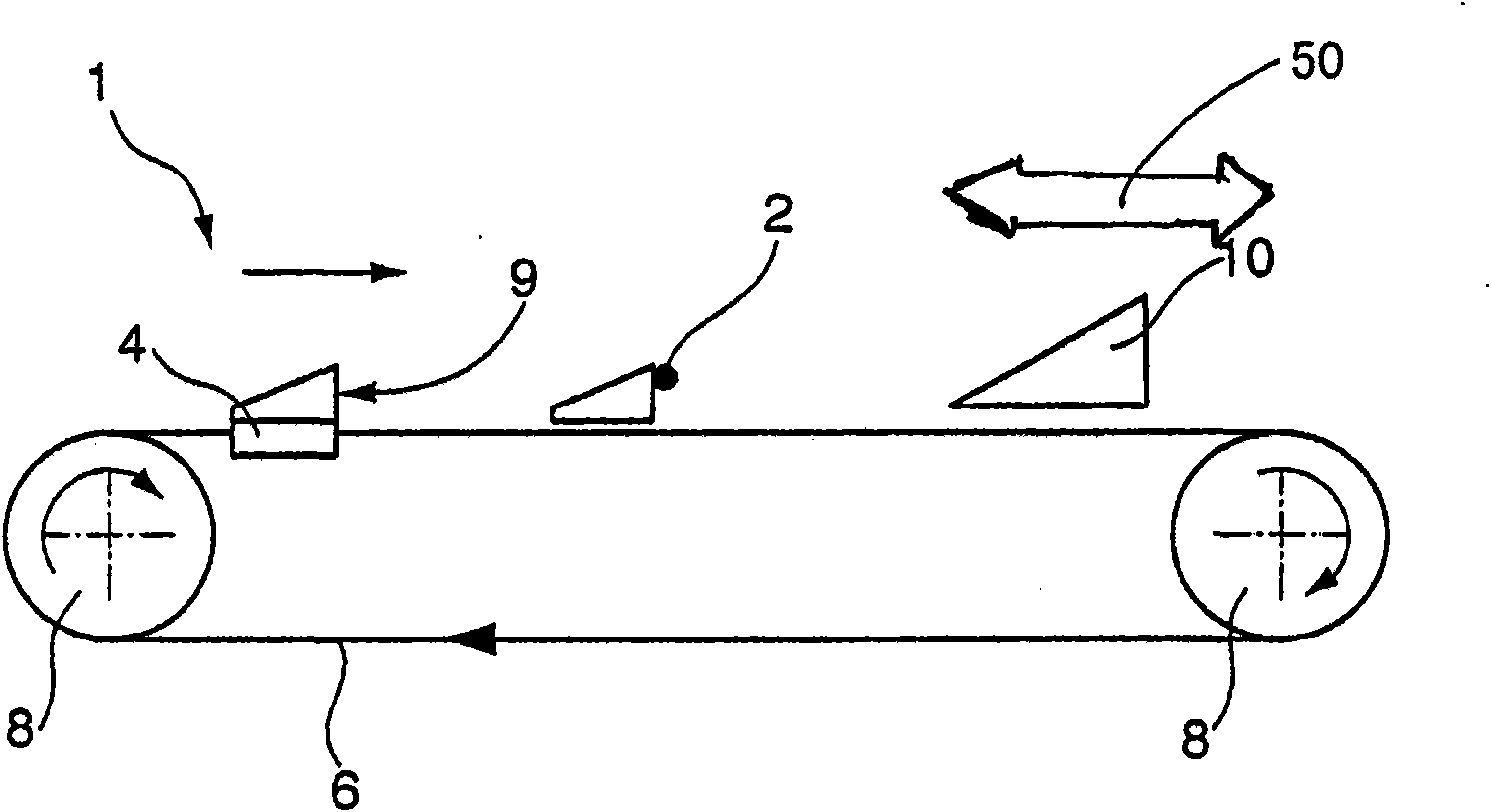
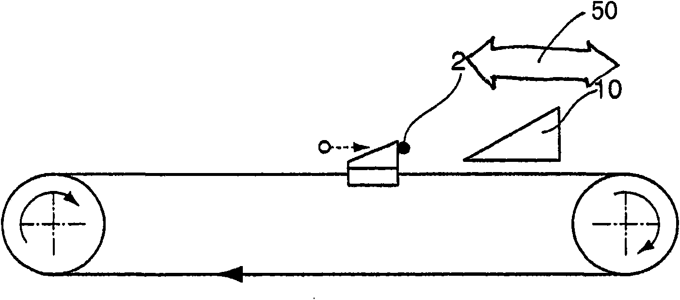
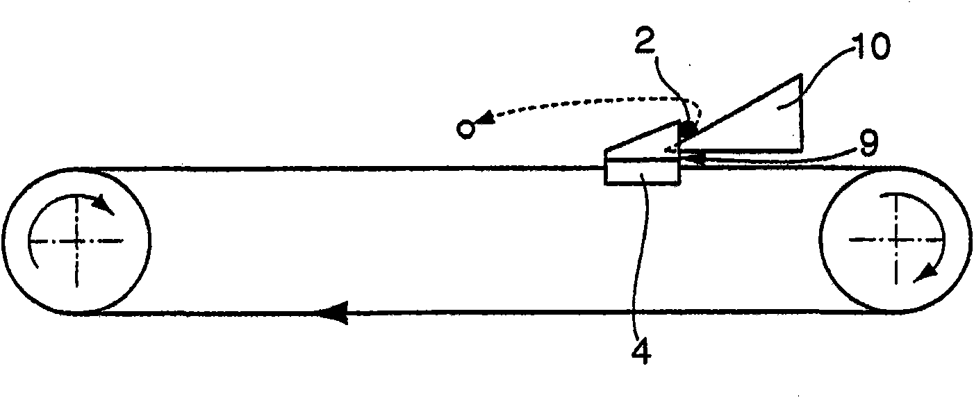
[0024] exist Figures 1a to 1c An embodiment of the slub forming device 1 according to the invention and its arrangement in a plane perpendicular to the thread path of the yarn to be texturized is schematically shown in FIG. The figures here show the lateral deflection of a filament 2 of the yarn out of its yarn path in order to form slubs during the crimping of the yarn. The slub forming device 1 has a driver 4 mounted on a cable 6 or belt of a diverting element. The cable 6 or the belt is guided around two deflectors 8 designed as wheels similarly to the case of a belt drive. At least one of the wheels is driven by an electric motor (not shown in FIG. 1 ), so that the reciprocating element with the driver 4 runs in a driven cycle (circumvention) in the direction indicated by the arrow.

[0025] The driver 4 has a thread guide 9 by which the thread 2 can be moved linearly away from the thread path by gripping the thread 2 when the driver 4 circulates, that is to say the thre...


PUM


Abstract

The invention relates to a device (1) for the production of fancy yarn during the texturizing of yarn by creating flames by way of short-term yarn transfer, having a motor-driven linear carrier (4) that can be moved away from the grain (35), wherein the carrier (4) has a thread guide (9) in order to create a yarn under-delivery by gripping a thread (2) of the yarn by way of the thread guide (9) and by lateral deflection of the yarn from the grain (35) thereof. For this purpose, trigger means (10) are provided, which are configured to release the thread (2) from the thread guide (9) at a deflection point positioned laterally from the grain (35) of the thread (2) in order to create the yarn delivery by means of abrupt termination of the deflection of the yarn. The trigger means (10) form a ramp, wherein the ramp is positioned such that the thread (2) can be pushed onto the ramp in the region of the deflection point by means of the thread guide (9), wherein the thread (2) may be lifted out of and/or lifted out above the thread guide (9) by pushing the same on for the release thereof. The device functions in a manner that is independent of the thread tension.

Description

technical field [0001] The present invention relates to a device (slub forming device) for making pattern yarn by creating slubs by using short-time yarn oversupply when crimping and texturing the yarn (slub forming device), having a A driver that moves away linearly, wherein the driver has a yarn guide to create a yarn undersupply by capturing the filaments with the yarn guide and deflecting the yarn laterally out of the yarn path; and also relating to A yarn processing machine having the device and a texturing unit (air texturing machine), for example with an air texturing nozzle. Background technique [0002] In air-jet texturing, monofilament yarn passes through an air-jet texturing nozzle (air-jet texturing nozzle) in a fully stretched state (FDY, Fully Drawn Yarn) in most cases to obtain a certain bulkiness. At this point at least two yarns are connected to each other. The two yarns are so-called core yarns and at least one so-called fancy thread which is arranged ar...

Claims


Application Information

Patent Timeline
Patent Type & Authority Applications(China)
IPC IPC(8): D02G1/16D02G3/34
CPCD02G1/00
Inventor C·马普V·西霍尔策G·卡拉尔斯兰
Owner SSM萨罗瑞士麦特雷有限公司
Why Eureka
Try Eureka