Water saving device

The technology of an appliance and a water hole, which is applied to water supply devices, indoor sanitary piping devices, spray devices, etc., can solve the problems of soaking, inability to obtain the purpose and function of the water supply hydrant, difficulty in constant volume or constant pressure, etc. Achieving the effect of beautiful appearance, inhibition of skin irritation, and great water saving effect

Active Publication Date: 2010-09-08
土井内数实
View PDF1 Cites 3 Cited by
  • Summary
  • Abstract
  • Description
  • Claims
  • Application Information

AI Technical Summary

Problems solved by technology

[0005] However, on the other hand, the water supply tap can be used to suppress the water discharged from the water passage hole of the above-mentioned water-saving component to save water, but the adjustment of the water supply valve is delicate and difficult to operate, and the water potential (water pressure) of the discharged water is relatively low. Strong, so there are disadvantages such as splashing of water after touching the user's skin to pollute the surrounding environment, or soaking the cuffs of clothes
In addition, for users with soft skin such as infants or women, there is a problem that the water with strong water potential stimulates the skin too much.
[0006] Of course, in order to suppress the water potential (water pressure) of the water, it is only necessary to operate the water stopcock. However, in this operation, the water stopcock is fully opened during the water supply restriction period, and the water stopcock is tightened outside the period. trouble
In addition, in this case, the original purpose, function, and effect of saving water by suppressing the discharge of the faucet without changing the usability of the water supply cock described above cannot be obtained.
[0007] Further, depending on various conditions such as geographic location conditions or floors of buildings, etc., or water supply conditions, the amount of water and water pressure sprayed from faucets, etc. are not constant, and water is not sprayed with a constant amount or constant pressure, so it is difficult to Make the water discharged from the water hole of the water saving part a constant amount or constant pressure

Method used


Image

  • Water saving device
  • Water saving device
  • Water saving device

Examples


Embodiment Construction

[0041] Hereinafter, although the water-saving appliance which concerns on this invention is demonstrated in detail based on drawing, this invention is not limited to this.

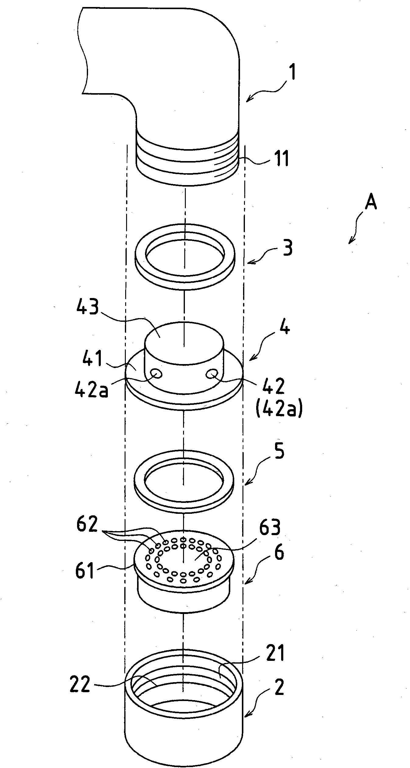
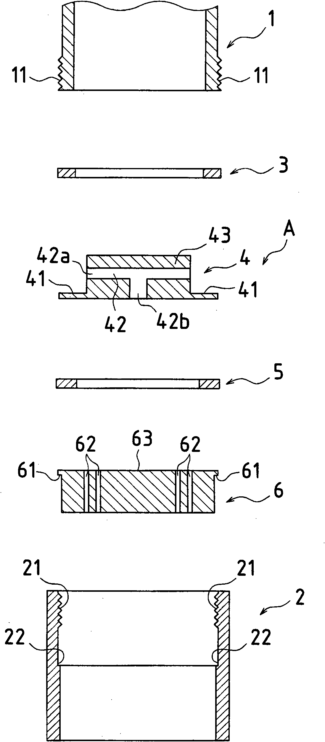
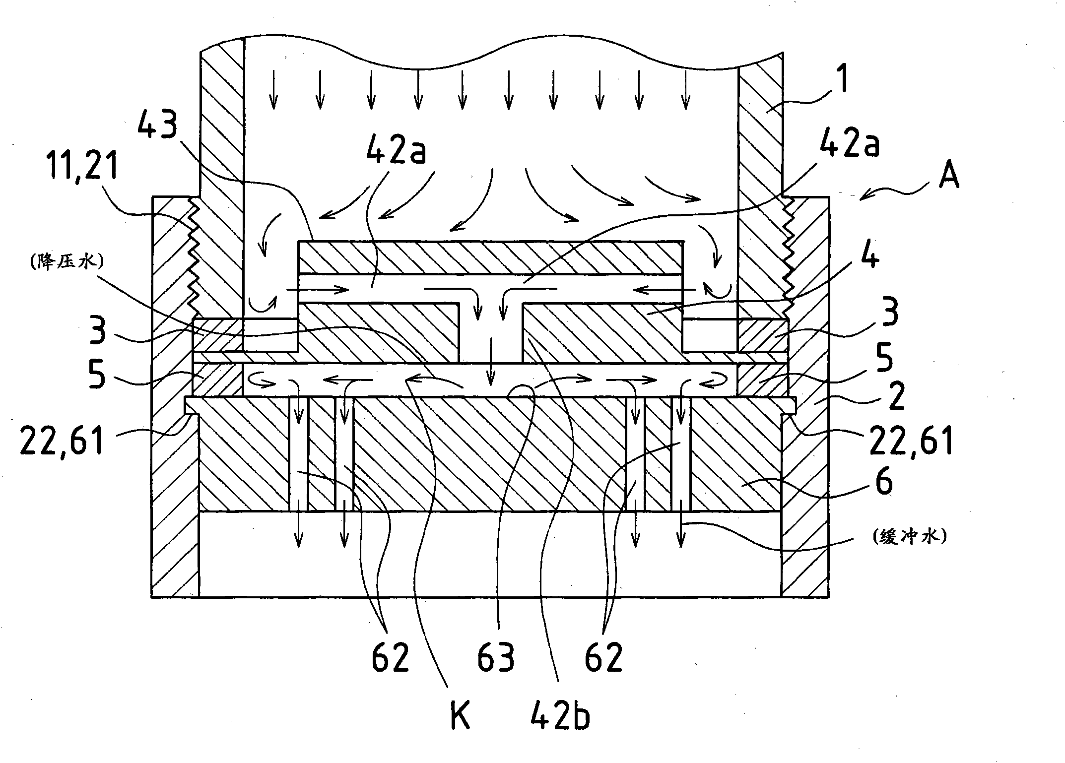
[0042] figure 1 It is an exploded perspective view showing one embodiment of the water-saving appliance A according to this embodiment, figure 2 Yes figure 1 longitudinal section view.

[0043] Here, in each figure, the same code|symbol is attached|subjected to the common member, and the repeated description is abbreviate|omitted.

[0044] The water-saving device A includes: a cylindrical attachment cover 2 that can be attached to a water supply port at the front end of a faucet 1 or the like that sprays water, and is open up and down; The member 6 is built in the mounting cover 2, and is provided with one or more drain holes 62, and a watertight gasket 3 for preventing water leakage between the faucet 1 and the mounting cover 2.

[0045] Furthermore, a pressure reducing member 4 serving as a pressure c...


PUM


Abstract

A water saving device having an installation cover (2) for installation on a faucet (1) etc., a water saving piece (6) installed within the installation cover (2) and having one or more water discharge holes (62), and a water-tight packing (3) for preventing water leakage from between the faucet (1) etc. and the installation cover (2). A pressure reduction piece (4) is placed between the installation cover (2) and the water saving piece (6), and the pressure reduction piece (4) has a flow path change hole (42) for forcibly changing the direction of water supplied from water discharge means, such as the faucet (1) etc., to reduce the pressure of the water.

Description

technical field [0001] The present invention relates to a water-saving device. The water-saving device is installed on a faucet (hereinafter simply referred to as a "faucet") that discharges water such as a rotary faucet, a mixing faucet, or an automatic faucet. And the body discharges water that is soft to the touch. Background technique [0002] In the past, there are known water-saving appliances that can save water by suppressing the discharge of water without changing the usability of the water supply cock. For example, the following water-saving appliances have been proposed as the above-mentioned water-saving appliances. The installation cover of the faucet and the like and the watertight gasket used to prevent water leakage between the above-mentioned faucet and the installation cover, and a cylindrical water-saving component (such as Refer to Patent Document 1). [0003] Patent Document 1: Japanese Patent Application Laid-Open No. 9-95985 [0004] Just by attachi...

Claims


Application Information

Patent Timeline
Patent Type & Authority Applications(China)
IPC IPC(8): E03C1/086
CPCE03C1/086B05B1/3073E03C2001/026E03C2001/0416
Inventor 土井内数实道胁裕
Owner 土井内数实
Why Eureka
Try Eureka