Novel strong lubrication floating core head assembly

A new technology of floating core, applied in the direction of the mandrel, etc., can solve the problems of fast wear of the floating core, accelerated wear of the floating core, and pollution of the surrounding environment, so as to avoid ring-shaped corrugated waste products and reduce power consumption , cost-saving effect

Active Publication Date: 2010-09-15
ZHEJIANG HAILIANG
View PDF2 Cites 7 Cited by
  • Summary
  • Abstract
  • Description
  • Claims
  • Application Information

AI Technical Summary

Problems solved by technology

[0003] In the traditional stretching process of the floating core head, there are two ways to lubricate the inner surface of the pipe: the first is that the lubricating oil is sprayed out through the oil injection hole at the front end of the hollow mandrel and adheres to the inner surface of the pipe to lubricate, Cooling effect, but in actual operation, in view of the difference in design and operation, there is a certain distance between the oil injection hole of the hollow core rod and the variable diameter working section of the floating core head, and the lubricating oil sprayed from the oil injection hole cannot directly enter the lubricating wedge. As a result, the lubricating oil stored in the lubricating wedge is insufficient, the lubrication is uneven, it is difficult to fully and effectively lubricate and take away the heat generated by deformation, the tensile force is increased, and the swimming core wears faster; The patent number "CN02215573.2" published on January 29th, and the patent titled "Drawing Die Device for Large-diameter Thin-walled Copper Pipe" proposed a drawing die for large-diameter precision thin-walled copper pipes device, the end of the stretching core in this patent is sequentially connected with a connector with an oil injection hole and a long mandrel with a lubricating oil through hole. When stretching, lubricating oil is sprayed out from the oil injection hole on the connector for lubrication. , its disadvantages are as mentioned above; the second is immersion lubrication, first put the pipe to be processed into the lubricating oil tank for soaking, then drain the lubricating oil in the pipe, and then lift the pipe to the loading rack of the stretching machine for The disadvantage of this method is that during the stretching process, the lubricating oil is easy to flow out of the pipe to pollute the surrounding environment and cause ineffective loss of the lubricating oil. Large, the wear of the moving core head is accelerated. For example, the patent No. "200720045387.8" published by the China National Patent Office on July 9, 2008, and the patent named "Tension Core Head of Hollow Metal Pipe" proposed a core The stretching core head with small head resistance adopts an upwardly inclined deformation section on the side of the stretching core head to solve the problem of high friction between the pipe and the stretching core head in the deformation section, large consumption of lubricating oil, and pipe stretching. The disadvantage of unstable size, but before stretching, it is necessary to inject an appropriate amount of lubricating oil into the inside of the pipe for lubrication. The disadvantages are as mentioned above
Therefore, in view of the problems exposed by the traditional floating core in the stretching process, it is necessary to propose a strong lubricating floating core assembly design to reduce the tensile force, improve the service life of the floating core, and And the purpose of energy saving and environmental protection

Method used


Image

  • Novel strong lubrication floating core head assembly
  • Novel strong lubrication floating core head assembly
  • Novel strong lubrication floating core head assembly

Examples


Embodiment Construction

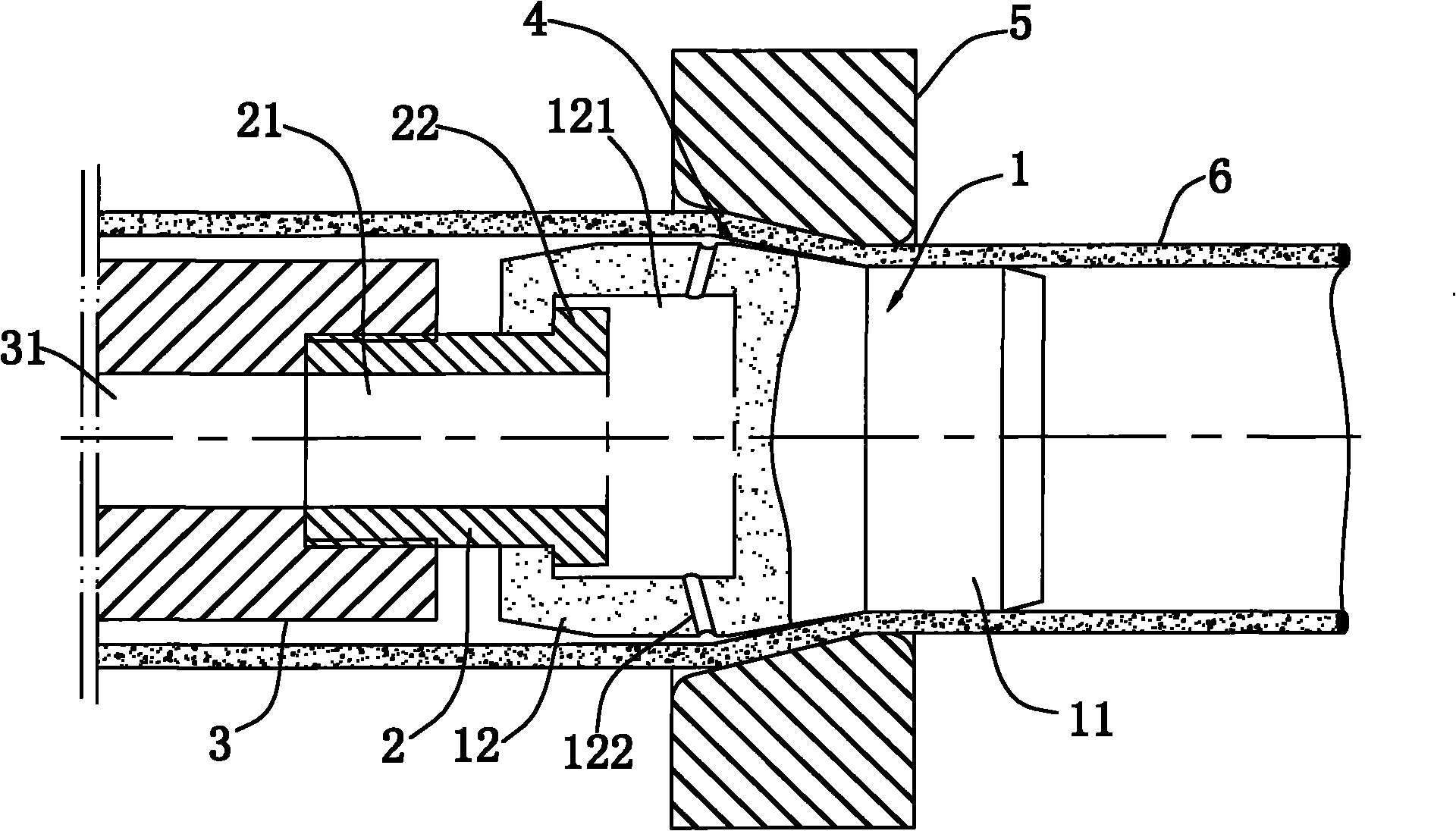
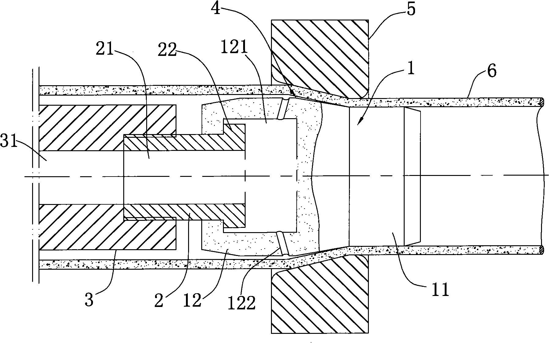
[0018] Such as figure 1 As shown, the present invention provides a novel strongly lubricated traveling mandrel assembly, comprising a stretching mandrel 3, a traveling mandrel 1 and a connecting screw 2 for connecting the drawing mandrel 3 and the traveling mandrel 1, The stretching mandrel 3 is provided with an oil passage I 31, the swimming core 1 is provided with an oil storage chamber 121, and the connecting screw 2 is provided with a communication oil passage I 31 and an oil storage chamber 121. There are several oil injection holes 122 communicated with the oil storage chamber 121 in the radial direction on the wall of the floating core head 1 . The floating core 1 is composed of a finishing section 11 for controlling the size of the pipe material 6 and a working section 12 for shaping and guiding. The working section 12 is connected with the connecting screw 2, and the oil storage chamber 121 is located in the working section. Inside section 12; the shape of working se...


PUM


Abstract

The invention discloses a novel strong lubrication floating core head assembly which comprises a stretching core bar, a floating core head and a connecting screw rod for connecting the stretching core bar and the floating core head, wherein an oil pore channel I is arranged in the stretching core bar; an oil storage chamber is arranged in the floating core head; an oil pore channel II which is used for communicating the oil pore channel I with the oil storage chamber is arranged in the connecting screw rod; and a plurality of oil spray through holes which are communicated with the oil storage chamber are radially and annularly distributed on the wall body of the floating core head. The structure and shape designs of the strong lubrication floating core head ensure that lubricating oil can be accurately and evenly sprayed into a lubrication wedge in the stretching process, the lubrication wedge has enough lubricating oil, and the hydrodynamic pressure in the lubrication wedge, namely, the lubrication wedge effect is improved, thereby reducing the electric energy consumption and the stretching force in the process of stretching straight pipes, improving the stretching efficiency of the pipes, prolonging the service life of the floating core head and having the advantages of energy saving and environment protection.

Description

technical field [0001] The invention relates to a lubricated floating core head assembly used for stretching straight pipes, and belongs to the technical field of design and manufacture of dies for metal pressure processing. Background technique [0002] At present, in the processing and manufacturing of straight metal pipes in China, the swimming core is generally used for drawing. The swimming core is mainly used for drawing copper tubes. It is used in conjunction with the pipe drawing die. The fixed connection achieves a balanced state through the friction force with the copper tube and the reaction force when the copper tube is deformed, so it is called the swimming core head. [0003] In the traditional stretching process of the floating core head, there are two ways to lubricate the inner surface of the pipe: the first is that the lubricating oil is sprayed out through the oil injection hole at the front end of the hollow mandrel and adheres to the inner surface of the...

Claims


Application Information

Patent Timeline
Patent Type & Authority Applications(China)
IPC IPC(8): B21C3/16B21C1/24
Inventor 狄大江赵学龙曹建国黄登科黄路稠刘水平魏连运王钊王霞
Owner ZHEJIANG HAILIANG
Why Eureka
Try Eureka