
Spindle motor

a spindle motor and spindle technology, applied in the direction of magnetic circuit rotating parts, instruments, magnetic circuit shape/form/construction, etc., can solve the problems of negative influence on the driving of the spindle motor, internal components may be deformed, and the spindle motor may not be able to achieve the effect of improving rigidity and increasing the storage space of lubricating fluid

Inactive Publication Date: 2014-07-03
SAMSUNG ELECTRO MECHANICS CO LTD
View PDF10 Cites 0 Cited by
  • Summary
  • Abstract
  • Description
  • Claims
  • Application Information

AI Technical Summary

Benefits of technology

The present invention provides a spindle motor with improved rigidity and a larger space for lubricating fluid. Additionally, it simplifies the manufacturing process and reduces costs by using a simpler design. The spindle motor can also increase the hydrodynamic pressure and improve resistance against external impacts.

Problems solved by technology

Due to this phenomenon, the hydrodynamic bearing may not generate pressure, and consequently, a problem in terms of the performance and lifespan of the spindle motor may be generated.
In addition, in the case in which an external impact, or the like, is applied during the driving of a spindle motor, internal components may be deformed, which may have a negative influence on the driving of the spindle motor.

Method used


Image

  • Spindle motor
  • Spindle motor
  • Spindle motor

Examples


Embodiment Construction

[0039]Hereinafter, embodiments of the present invention will be described in detail with reference to the accompanying drawings.

[0040]The invention may, however, be embodied in many different forms and should not be construed as being limited to the embodiments set forth herein. Rather, these embodiments are provided so that this disclosure will be thorough and complete, and will fully convey the scope of the invention to those skilled in the art.

[0041]In the drawings, the shapes and dimensions of components maybe exaggerated for clarity, and the same reference numerals will be used throughout to designate the same or like components.

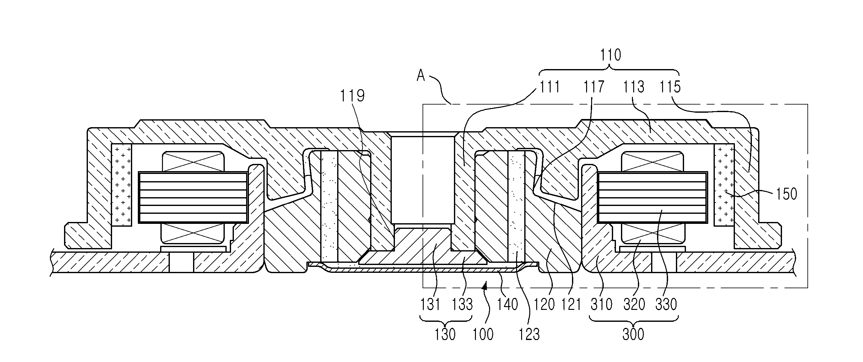
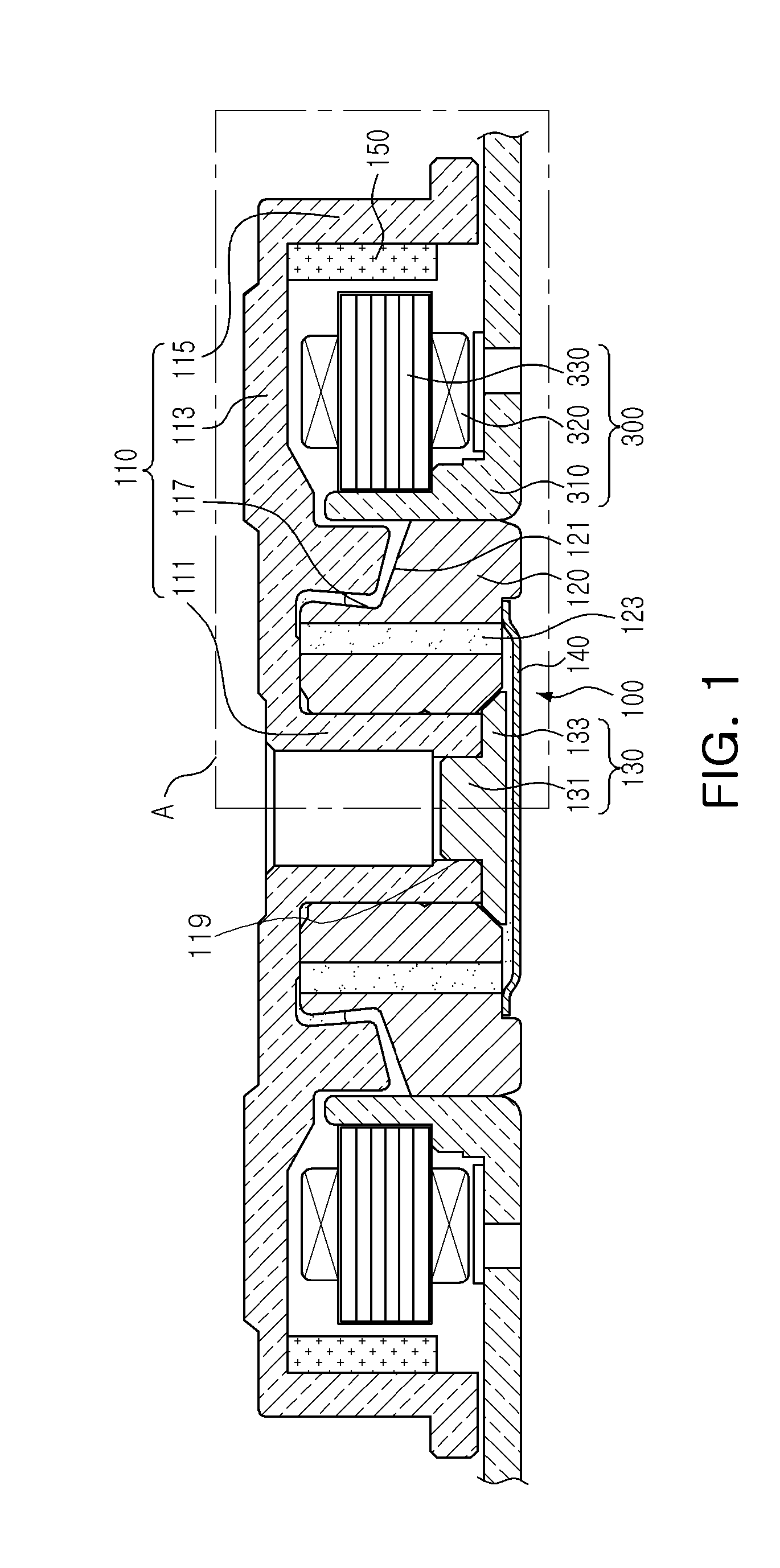
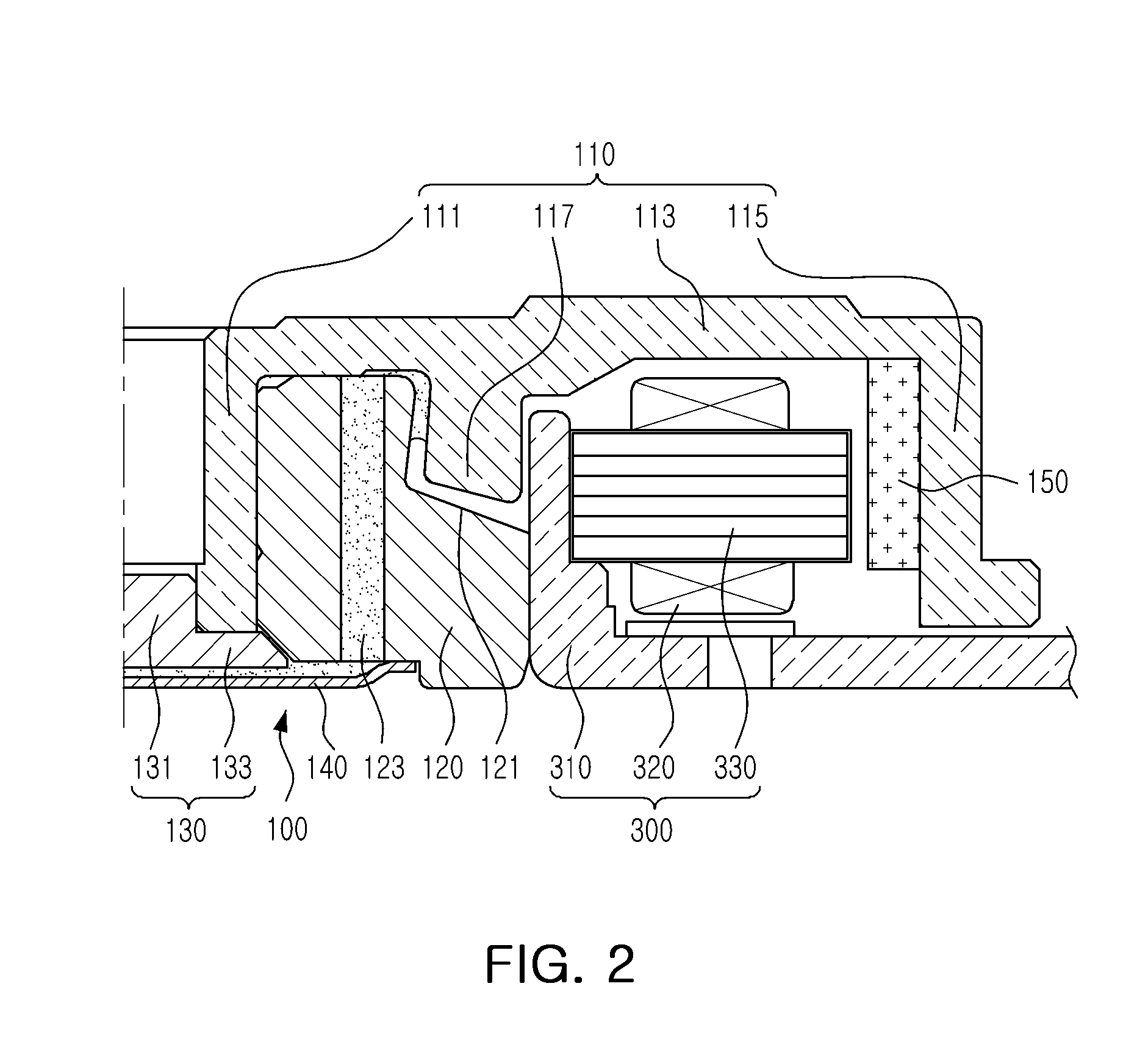
[0042]FIG. 1 is a schematic cross-sectional view showing a spindle motor according to an embodiment of the present invention; and FIG. 2 is an enlarged cross-sectional view of part A of FIG. 1.

[0043]FIGS. 3 through 6 are half cross-sectional views showing modified examples of a taper structure for sealing a lubricating fluid in the spindle motor accordi...


PUM


Abstract

There is provided a spindle motor including: a rotating member including a shaft having a fixation groove provided in a lower portion thereof, a hub base extended from an upper end of the shaft in an outer radial direction, and a magnet support part extended downwardly from an outer edge of the hub base in an axial direction; a sleeve rotatably supporting the rotating member and including a reception groove depressed downwardly from an upper surface thereof in the axial direction; and a stopper member including a fixation part inserted into the fixation groove and a flange part extended from the fixation part in the outer radial direction, wherein the hub base includes a protrusion part protruding from one surface of the hub base and received in the reception groove.

Description

CROSS-REFERENCE TO RELATED APPLICATIONS[0001]This application claims the priority of Korean Patent Application No. 10-2012-0156966 filed on Dec. 28, 2012, in the Korean Intellectual Property Office, the disclosure of which is incorporated herein by reference.BACKGROUND OF THE INVENTION[0002]1. Field of the Invention[0003]The present invention relates to a spindle motor.[0004]2. Description of the Related Art[0005]A hard disk drive (HDD), an information storage device, reads data stored on a disk or writes data to a disk using a read / write head.[0006]The hard disk drive requires a disk driving device capable of driving the disk. In a disk driving device, a spindle motor is commonly used.[0007]This spindle motor uses a hydrodynamic bearing assembly. A shaft, a rotating member of the hydrodynamic bearing assembly, and a sleeve, a fixed member thereof, have a lubricating fluid interposed therebetween, such that the shaft is supported by fluid pressure generated in the lubricating fluid....

Claims


Application Information

Patent Timeline
IPC IPC(8): H02K7/08H02K1/27
CPCH02K1/2786H02K7/08H02K5/1675G11B19/2009F16C2370/12F16C33/745F16C43/02F16C17/107G11B19/20H02K5/173F16C17/10F16C33/10
Inventor SMIRNOV, VIATCHESLAV
Owner SAMSUNG ELECTRO MECHANICS CO LTD
Learn More