
Device for dieless progressive molding of metal plate

A progressive forming and metal sheet technology, applied in the field of mechanical processing, can solve the problems of mandrel and complex structure, simple shape, etc., and achieve the effect of less production preparation time, simple structure and low processing cost

Inactive Publication Date: 2010-09-15
NORTHWESTERN POLYTECHNICAL UNIV
View PDF2 Cites 9 Cited by
  • Summary
  • Abstract
  • Description
  • Claims
  • Application Information

AI Technical Summary

Problems solved by technology

[0004] In order to overcome the shortcomings of existing devices, such as the simple shape of the formed parts, the need for a mandrel and the complex structure, the present invention proposes a device for dieless progressive forming of sheet metal

Method used


Image

  • Device for dieless progressive molding of metal plate
  • Device for dieless progressive molding of metal plate
  • Device for dieless progressive molding of metal plate

Examples


Embodiment 1

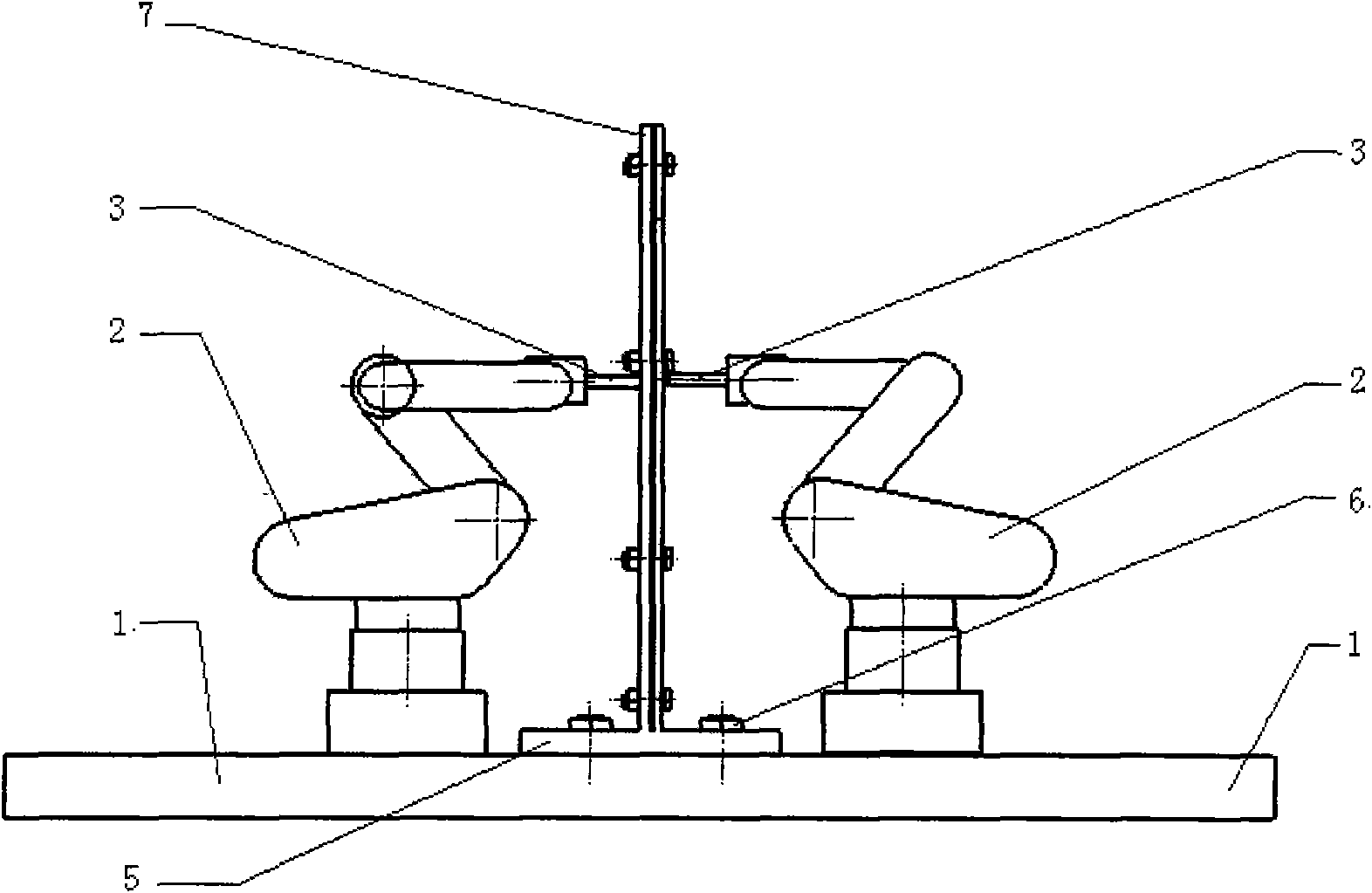
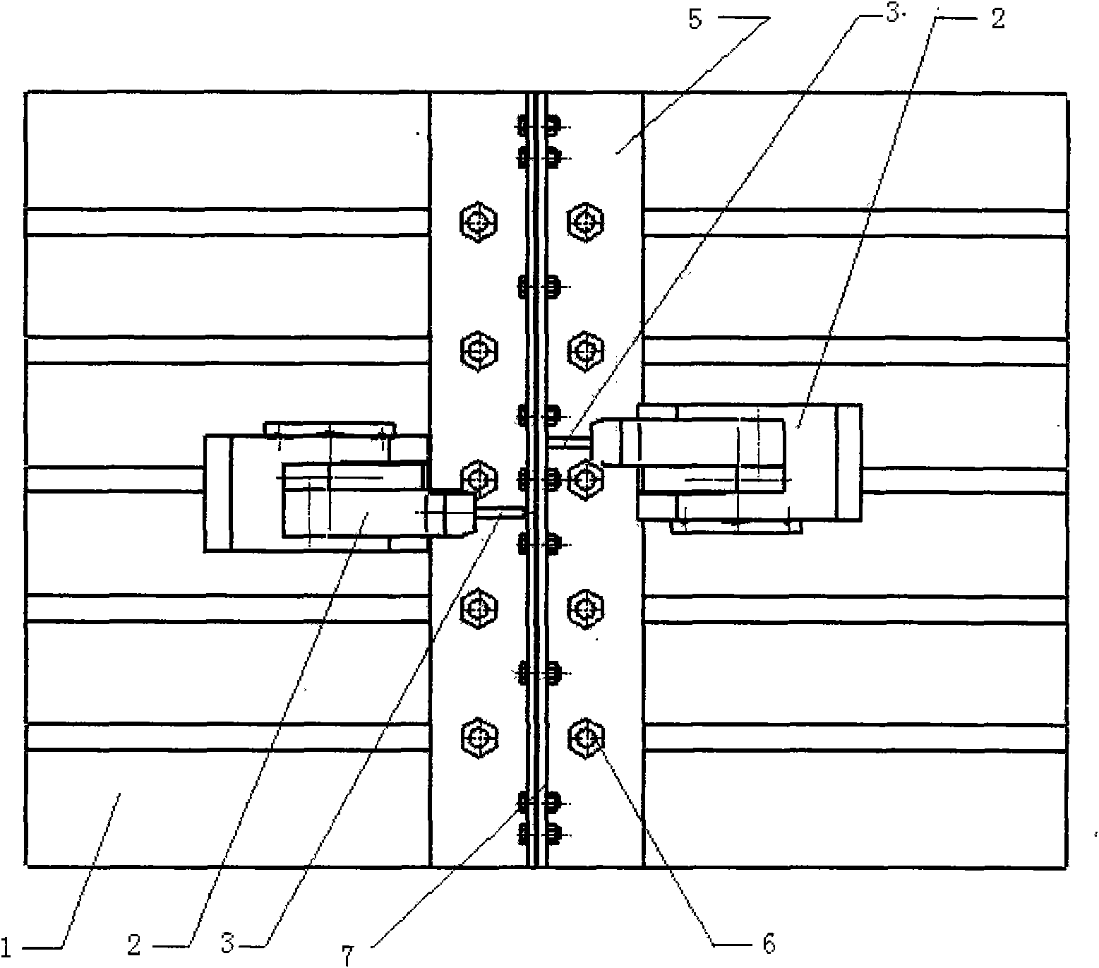
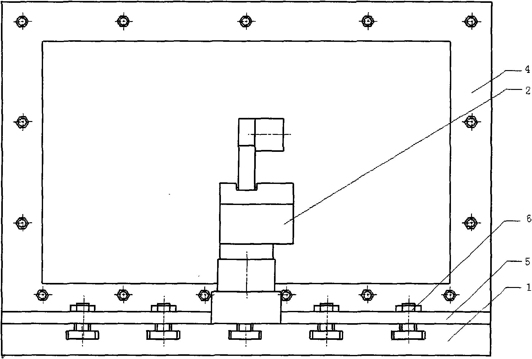
[0023] This embodiment is a device for dieless progressive forming of sheet metal, which includes two parts. One part consists of a platform 1, two industrial manipulators 2 and their control systems, and two forming tool heads 3. The other part is a blank clamping frame 7 made up of a blank clamping frame 4 and a bottom plate 5 . as attached figure 1 , attached figure 2 And attached image 3 shown. The platform 1 is a rectangular flat plate, and the plate clamping frame 7 is fixed in the middle of the platform 1 in the longitudinal direction by bolts. Two industrial manipulators 2 are arranged on both sides of the sheet metal clamping frame 7, and are installed on the platform 1 through fixing bolts. The dieless incremental forming device described in this embodiment forms a 1 mm thick 2A12 annealed aluminum alloy plate, and the outer dimension of the plate is 300 mm*500 mm.

[0024] In this embodiment, parallel standard T-shaped grooves are evenly distributed on the t...

Embodiment 2

[0031] This embodiment is a device for dieless progressive forming of sheet metal, which includes two parts. One part consists of a platform 1, two industrial manipulators 2 and their control systems, and two forming tool heads 3. The other part is a blank clamping frame 7 made up of a blank clamping frame 4 and a bottom plate 5 . as attached figure 1 , attached figure 2 And attached image 3 shown. The platform 1 is a rectangular flat plate, and the plate clamping frame 7 is fixed in the middle of the platform 1 in the longitudinal direction by bolts. Two industrial manipulators 2 are arranged on both sides of the sheet metal clamping frame 7, and are installed on the platform 1 through fixing bolts. The dieless incremental forming device described in this embodiment forms a 1.5mm thick 7075 aluminum alloy plate, and the outer dimension of the plate is 400mm*600mm.

[0032] In this embodiment, parallel standard T-shaped grooves are evenly distributed on the table surfa...


PUM


Abstract

The invention relates to a device for dieless progressive molding of a metal plate, which comprises two industrial manipulators (2), molding tool heads (3), a plate clamping frame (7) and a platform (1), wherein the plate clamping frame is fixed in the middle of the platform; the two industrial manipulators are respectively distributed at both sides of the plate clamping frame (7); and one ends of the two molding tool heads are connected with the industrial manipulators (2), and the other ends are in contact with a plate on the plate clamping frame (7). At work, the industrial manipulators (2) drive the molding tool heads (3) to move to respectively exert both sides of the plate, the molding on the whole plate can be realized, the molding or correction of a small local area on the plate can be also realized, and various metal plate parts meanwhile containing convex and concave curved surfaces are molded without a die and have larger processing flexibility. The invention has simple structure and low use cost and is suitable for the molding processing of parts in small batch with various complicated curved surfaces, such as automobile covering element, aerospace aircraft shell, and the like.

Description

1. Technical field [0001] The invention relates to the field of mechanical processing, in particular to a device for dieless progressive forming of sheet metal. 2. Background technology [0002] Usually in traditional production, the manufacture of sheet metal parts with complex curved surfaces needs to be processed with punches and dies. However, the design and manufacture cycle of the punch and the die is long and the cost is high, so this device is suitable for mass production, but not suitable for the production of single small batch parts and the trial production of new product prototype systems. At the same time, the types and complexity of parts formed by traditional molds have great limitations. Moreover, since springback is inevitable in the sheet metal forming process, in order to compensate the impact of springback on the precision of formed parts, it takes a lot of time and manpower to repeatedly correct the die and punch in actual production. Therefore, in ord...

Claims


Application Information

Patent Timeline
Patent Type & Authority Applications(China)
IPC IPC(8): B21D25/00B21D37/00B21D25/04
Inventor 王永军武伟超
Owner NORTHWESTERN POLYTECHNICAL UNIV
Learn More