

Lifter for main roller and method for transporting the main roller
A technology of lifts and main rollers, applied in the field of lifts, can solve the problems of difficult positioning work weight, poor workability, long working time, etc., and achieve efficient installation or disassembly operations, easy position adjustment, and reasonable moving out operations.
- Summary
- Abstract
- Description
- Claims
- Application Information
AI Technical Summary
Problems solved by technology
Method used
Image

Examples
Embodiment Construction
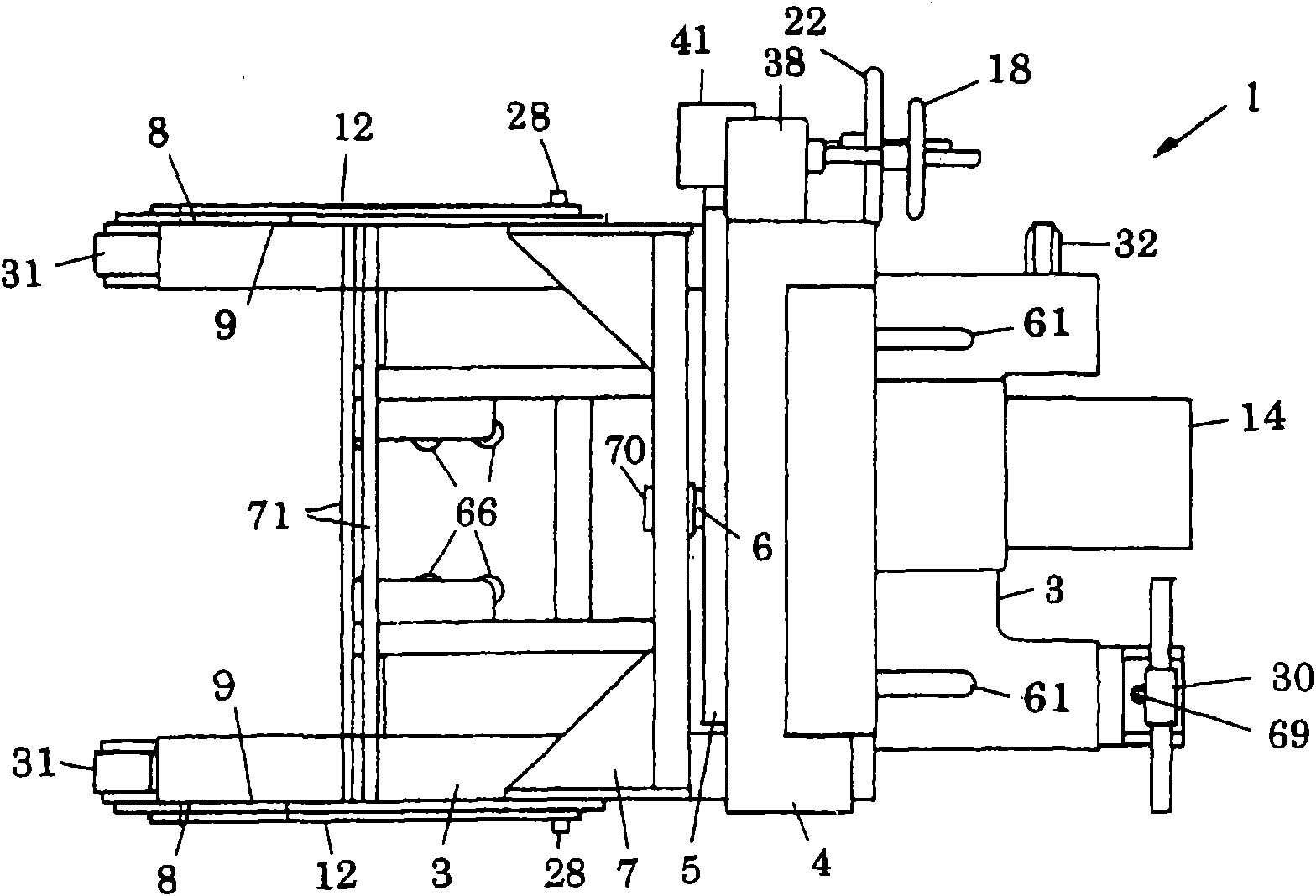
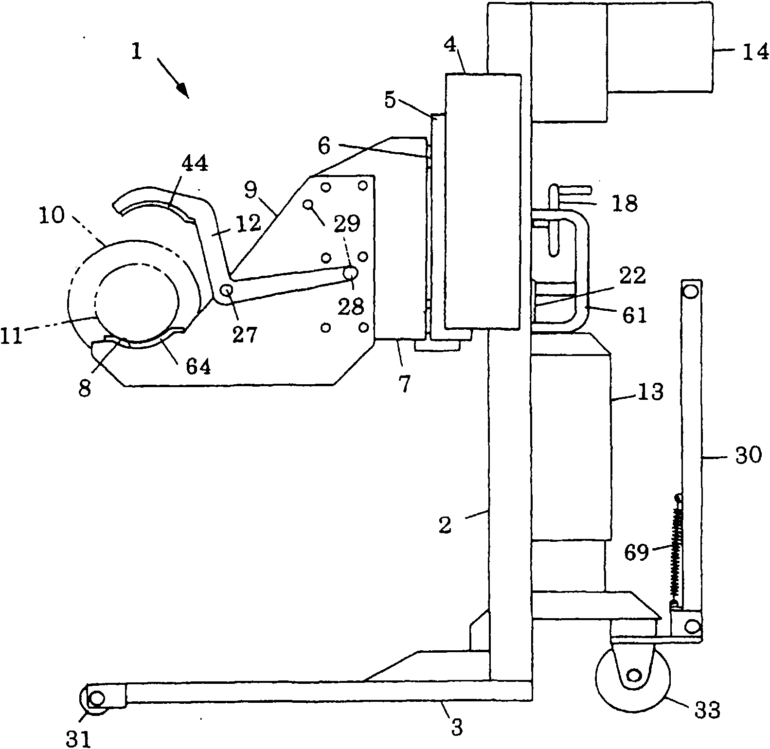
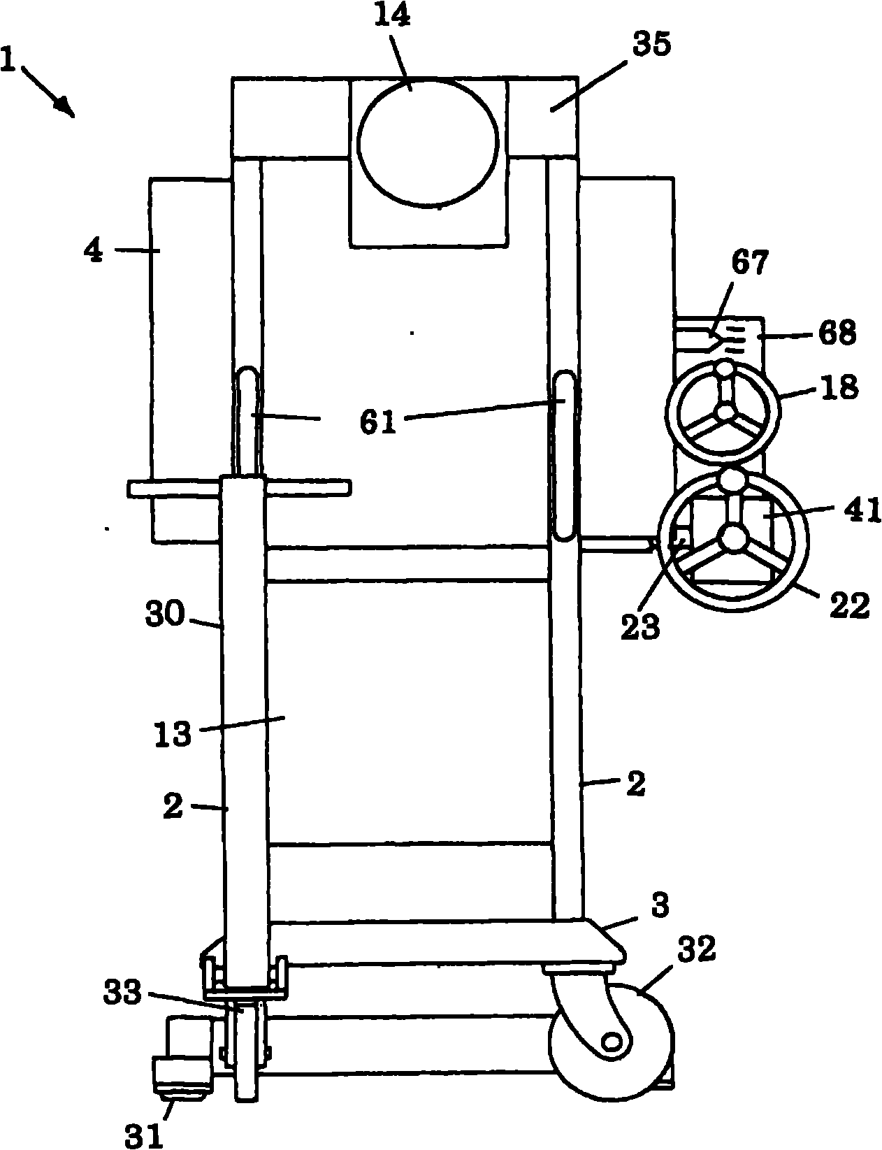
[0036] Figure 1 to Figure 3 shows the overall structure of the main roll lifter 1 according to the present invention, Figure 4 to Figure 9 Indicates the structure of each part. Such as Figure 1 to Figure 3 As shown, the main roller lifter 1 is used to support the main roller 10 of the wire saw as the conveying and holding object, and has: a moving vehicle 3, an elevating part 4, a lateral moving part 5, a horizontal extending part 7, and a pair of forks. 9, and pressing bar 12.
[0037] The mobile vehicle 3 is a traction or hand-push type, and is composed of wheels 31 fixed in the direction of the front left and right positions, casters 32 located on one side of the rear left and right positions, and a free wheel 33 with a handle 30 on the other side that can change the direction. , there is a pair of left and right pillars 2 for lifting guidance at a slightly rear position. The handle 30 is pre-tensioned by a tension spring 69 to keep it upright. Moreover, the handle ...
PUM
 Abstract
Description
Claims
Application Information