Connecting structure of combined beam and concrete bearing cross beam

A technology for connecting structures and concrete, applied in the direction of bridges, bridge parts, bridge construction, etc., can solve the problems of cracks in the middle fulcrum bridge deck, difficult construction, inconvenient local repair or renovation, etc., to achieve good adjustability and reduce impact. Effect

Inactive Publication Date: 2010-09-15
TONGJI UNIV
View PDF5 Cites 12 Cited by
  • Summary
  • Abstract
  • Description
  • Claims
  • Application Information

AI Technical Summary

Problems solved by technology

[0002] The steel and concrete continuous composite girder bridge has a large spanning capacity and effectively utilizes the advantages of the composite structure, but the beam body on the middle pier bears a large negative bending moment, and the method of adding longitudinal prestressed tendons to improve its stress There are defects such as difficult construction, inconvenient partial repair or renovation; the shrinkage, creep and temperature deformation of the concrete bridge deck are constrained by the steel beam, and it is also easy to cause tensile stress in the bridge deck at the middle fulcrum and then produce cracks. Therefore, steel and concrete are continuous. How to bear the tensile stress and prevent the occurrence of harmful cracks on the concrete deck of composite girder bridges is still a difficult problem to be solved

Method used


Image

  • Connecting structure of combined beam and concrete bearing cross beam
  • Connecting structure of combined beam and concrete bearing cross beam
  • Connecting structure of combined beam and concrete bearing cross beam

Examples


Embodiment Construction

[0033] The present invention will be further described below in conjunction with the embodiments shown in the accompanying drawings.

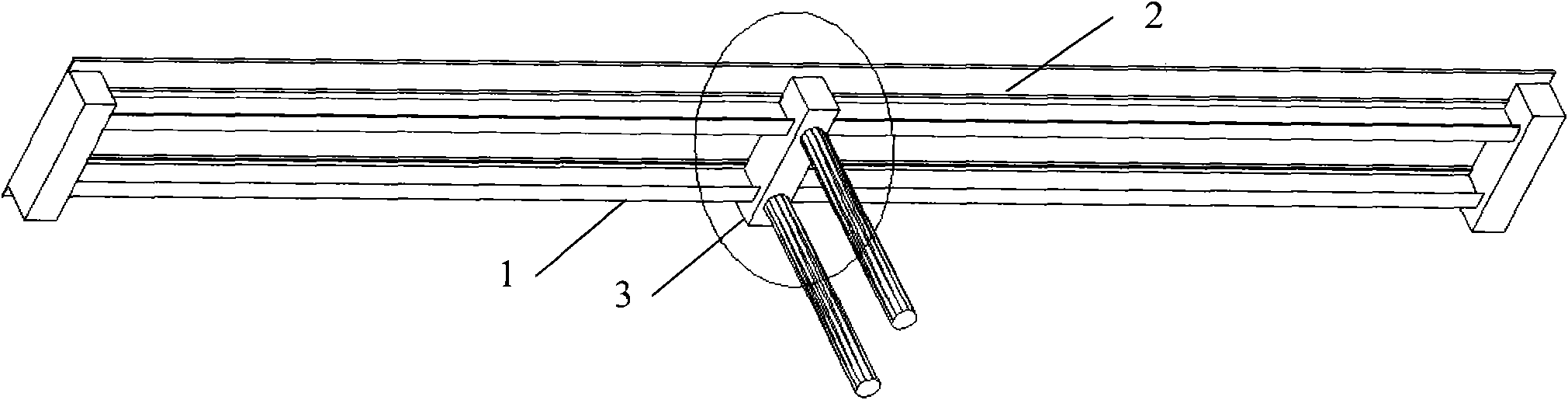
[0034] Such as figure 1 As shown, the steel beam 1 is discontinuous at the middle fulcrum, and a concrete support beam 3 is arranged at the discontinuity.

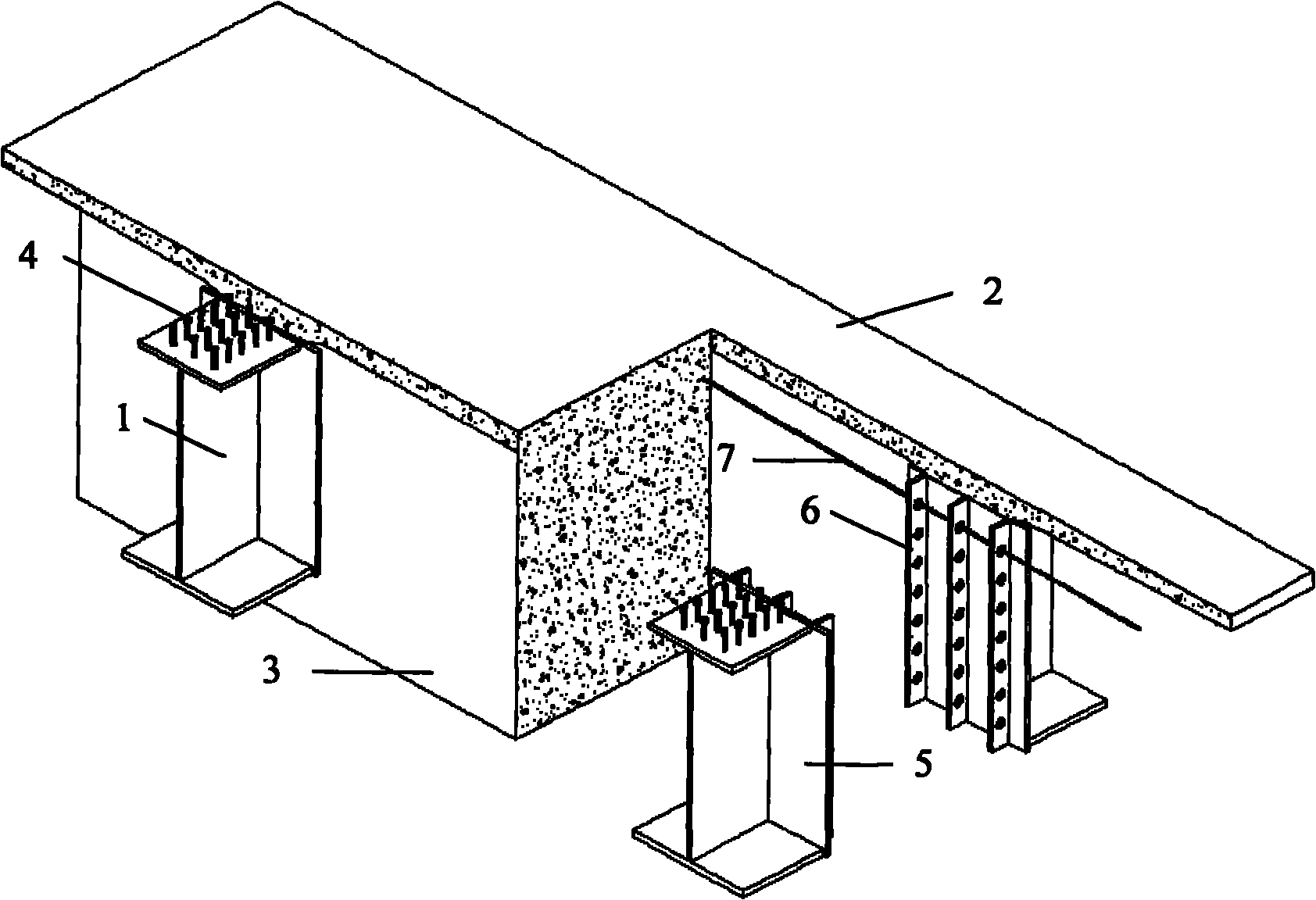
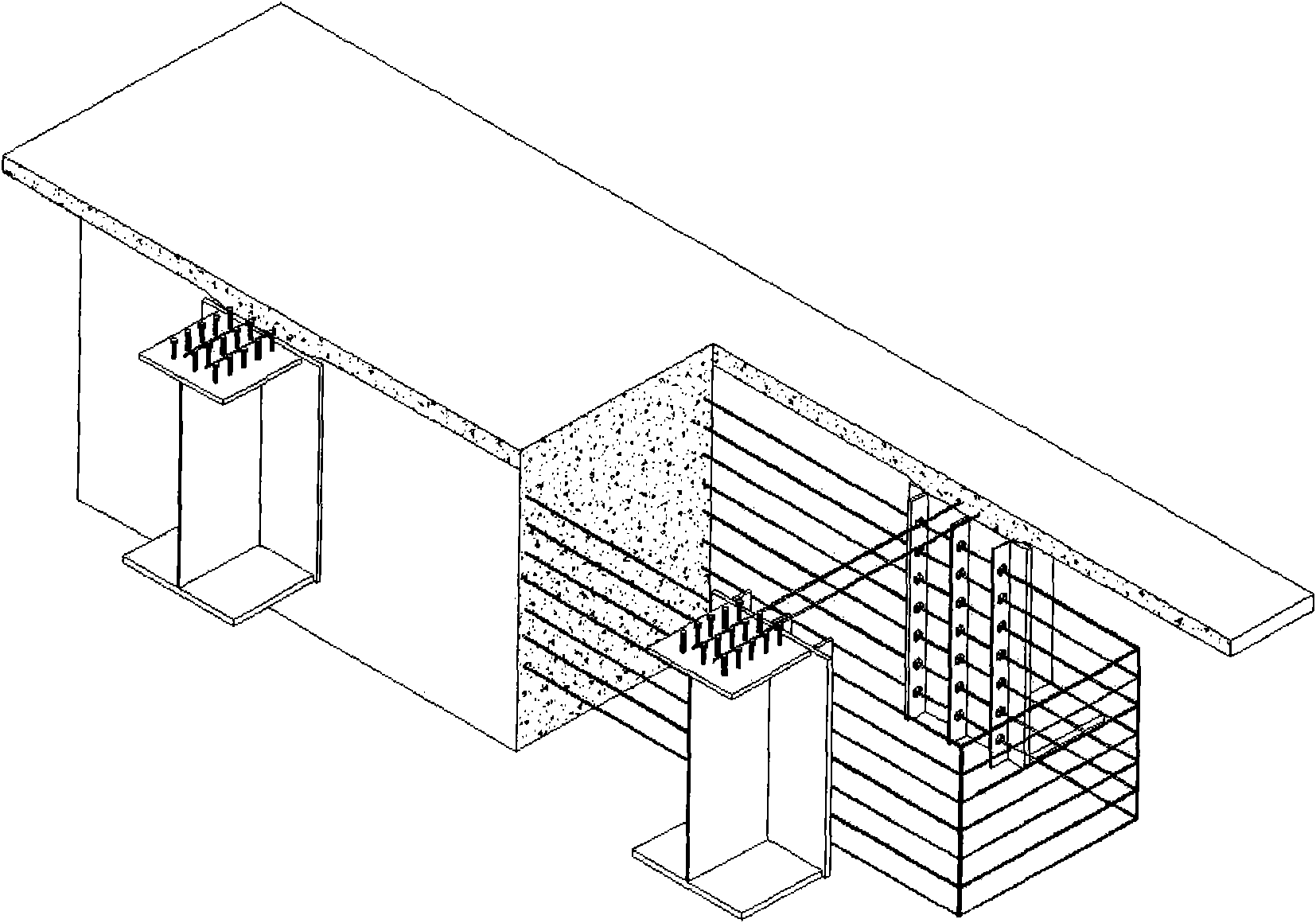
[0035] Such as figure 2 As shown, it is a structural schematic view of the connection structure between the composite beam and the concrete support beam of the present invention, wherein: the steel beam 1 and the concrete bridge deck 2 are connected by welding studs 4 or perforated plates (the perforated plate structure and perforated plate used here 6 similar in structure); an end plate 5 is set at the end of the steel beam 1, and the end plate 5 is welded with the flange and web of the steel beam 1, and the end plate 5 is welded with Figure 4 The perforated plate 6 shown is used to connect the steel beam 1 and the concrete supporting beam 3, so as to transmit the shear force and bendi...


PUM


Abstract

The invention discloses a connecting structure of a combined beam and a concrete supporting cross beam, comprising a steel girder and a concrete supporting cross beam, wherein the steel girder is disconnected at an intermediate pivot and is connected with the concrete supporting beam; an end plate is arranged at the end part of the steel girder and is provided with an open pore plate or is connected with the steel girder and the concrete supporting cross beam through weld screws so as to transfer the shearing force and the bending moment of a beam body; constructional steel bars are arranged in the concrete supporting cross beam; the constructional steel bars and a main forced steel bar form a steel reinforcement cage together; and a concrete pier is provided with a support seat which is supported on the bottom of the concrete supporting cross beam. The connecting structure reduces the tensile stress of a bridge panel in a negative bending moment area, caused by the shrinkage, the creep and the temperature of the concrete, and has concise and definite force transfer; and in addition, the prestress is not required to apply on the negative bending moment area and a bent cap is omitted. A steel structure is not required for welding on site and the adjustability of the distribution position of the pier is favorable.

Description

technical field [0001] The invention belongs to the technical field of bridge engineering and relates to a connection structure between a composite beam and a concrete supporting beam. Background technique [0002] The steel and concrete continuous composite girder bridge has a large spanning capacity and effectively utilizes the advantages of the composite structure, but the beam body on the middle pier bears a large negative bending moment, and the method of adding longitudinal prestressed tendons to improve its stress There are defects such as difficult construction, inconvenient partial repair or renovation; the shrinkage, creep and temperature deformation of the concrete bridge deck are constrained by the steel beam, and it is also easy to cause tensile stress in the bridge deck at the middle fulcrum and then produce cracks. Therefore, steel and concrete are continuous. How to bear the tensile stress and prevent the occurrence of harmful cracks on the concrete deck of c...

Claims


Application Information

Patent Timeline
Patent Type & Authority Applications(China)
IPC IPC(8): E01D19/00
Inventor 刘玉擎罗杰刘荣王戈
Owner TONGJI UNIV
Why Eureka
Try Eureka