

Reinforced concrete frame node
A technology of reinforced concrete and reinforced concrete beams, which is applied to building components, floor slabs, buildings, etc., can solve the problems of difficult cross-sectional size and longitudinal reinforcement ratio, and achieve the effect of preventing continuous collapse
- Summary
- Abstract
- Description
- Claims
- Application Information
AI Technical Summary
Problems solved by technology
Method used
Image

Examples
Embodiment 1
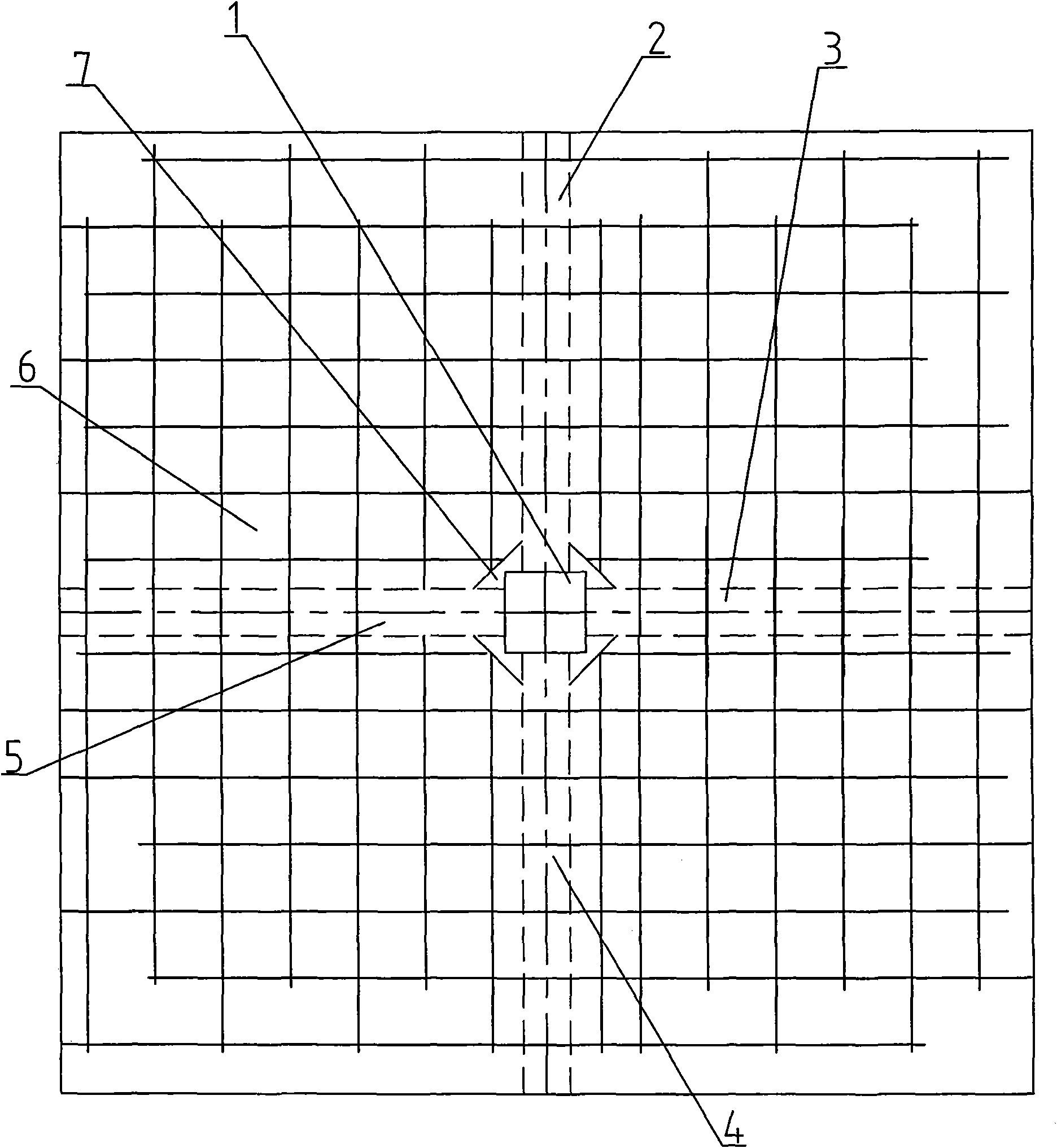
[0019] A reinforced concrete frame joint, see attached figure 1 , in the figure, a reinforced concrete column 1, a first reinforced concrete beam 2, a second reinforced concrete beam 3, a third reinforced concrete beam 4, a fourth reinforced concrete beam 5, a reinforced concrete floor 6, and a corner joint 7.
[0020] The reinforced concrete floor 6 around the intersection of the reinforced concrete column 1 and the reinforced concrete beam is provided with open angle joints 7 on the steel bars, and the open angle joints 7 are broken with the steel bars at the intersection of the reinforced concrete column 1 and the reinforced concrete beam. open state.
[0021] In this embodiment, the intersection points between the reinforced concrete column 1 and the first reinforced concrete beam 2, the second reinforced concrete beam 3, the third reinforced concrete beam 4 and the fourth reinforced concrete beam 5 are in the shape of a "cross" cross structure, and The corner joint 7 is ...
Embodiment 2
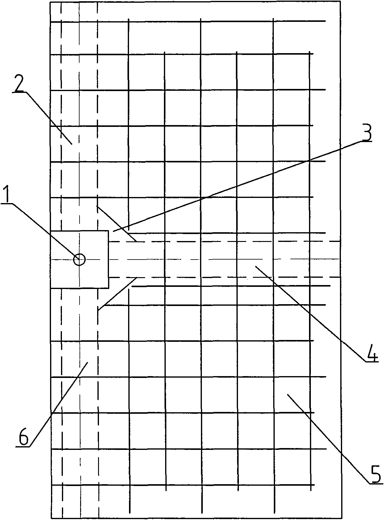
[0026] A reinforced concrete frame joint, see attached figure 2 , in the figure: reinforced concrete column 1, first reinforced concrete beam 2, open angle joint 3, second reinforced concrete beam 4, reinforced concrete floor slab 5, third reinforced concrete beam 6.
[0027] The reinforced concrete floor slab 5 around the intersection of the reinforced concrete column 1 and the reinforced concrete beam is provided with open angle joints 3 on the steel bars, and the open angle joints 3 are broken with the steel bars at the intersection of the reinforced concrete column 1 and the reinforced concrete beam. open state.
[0028] In this embodiment, the intersection of the reinforced concrete column 1 and the first reinforced concrete beam 2, the second reinforced concrete beam 4 and the third reinforced concrete beam 6 is a "T" cross structure, and the open angle joint 3 is placed in the intersecting reinforced concrete beam. Between the angles between the beams; that is: the re...
Embodiment 3
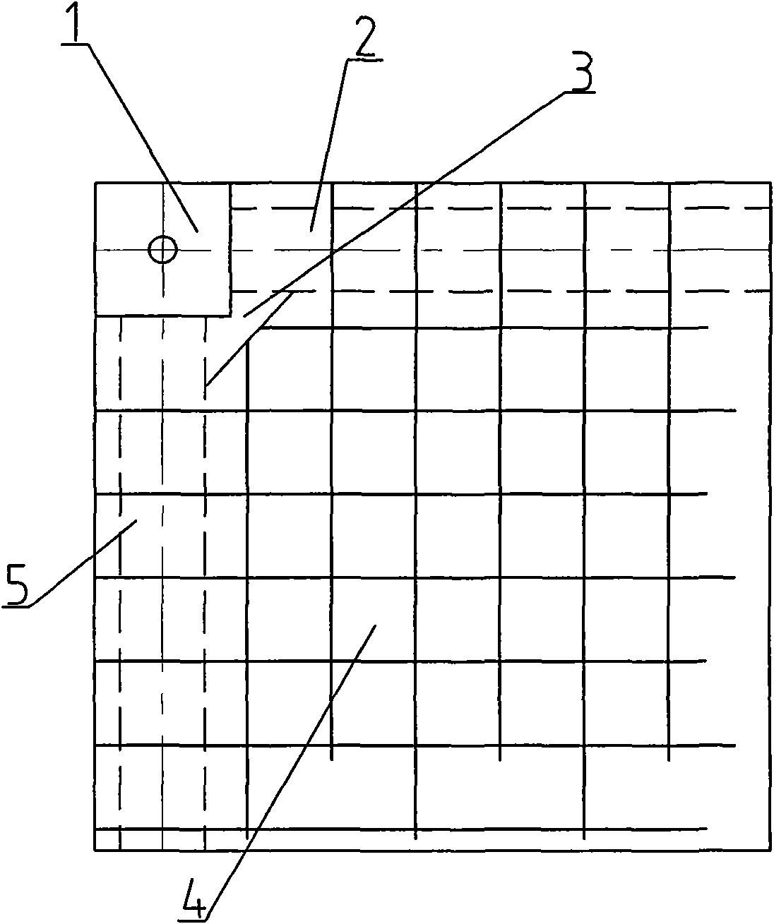
[0033] A reinforced concrete frame joint, see attached image 3 , in the figure: reinforced concrete column 1, first reinforced concrete beam 2, corner joint 3, reinforced concrete floor slab 4, second reinforced concrete beam 5.
[0034] In this embodiment, the reinforced concrete column 1 is located at the intersection of two reinforced concrete beams, that is, as image 3 As shown, the reinforced concrete column 1 is located at the intersection of the first reinforced concrete beam 2 and the second reinforced concrete beam 5, and the open angle joint 3 is placed in the steel bar between the angle between the first reinforced concrete beam 2 and the second reinforced concrete beam 5 Concrete floor 4 on.
[0035]For the existing cast-in-place reinforced concrete frame structure, cutting equipment can be used to cut the corner joint 3 on site, and the top reinforcement on the reinforced concrete floor 4 at the intersection of the reinforced concrete column 1 and the reinforce...
PUM
 Abstract
Description
Claims
Application Information