Rod type hydraulic linkage mechanism suitable for resisting progressive collapse of steel-concrete combined structure

A technology of combined structure and linkage mechanism, which is applied to building components, building structures, protective buildings/shelters, etc., can solve the problems of continuous structural collapse, failure to meet continuous collapse resistance, and failure to consider structural effects. The force transmission mechanism is clear, the continuous collapse is avoided, and the structure is simple.

Active Publication Date: 2021-06-04
TONGJI UNIV
View PDF6 Cites 0 Cited by
  • Summary
  • Abstract
  • Description
  • Claims
  • Application Information

AI Technical Summary

Problems solved by technology

However, because the current building design codes do not consider the effects of accidents (such as explosions, impacts, etc.) on the structure, a large number of existing and newly built composite structures cannot meet the requirements for resistance to progressive collapse.
[0003] Among them, after the concrete-filled steel tube convex corner column in the composite structure fails under the action of an accident, the steel beams connected to it cannot provide an additional effective anti-collapse force transmission path, which is particularly likely to lead to continuous collapse of the structure. However, the existing anti-collapse Technology still lacks practical and effective measures for convex corner columns

Method used


Image

  • Rod type hydraulic linkage mechanism suitable for resisting progressive collapse of steel-concrete combined structure
  • Rod type hydraulic linkage mechanism suitable for resisting progressive collapse of steel-concrete combined structure
  • Rod type hydraulic linkage mechanism suitable for resisting progressive collapse of steel-concrete combined structure

Examples


Embodiment

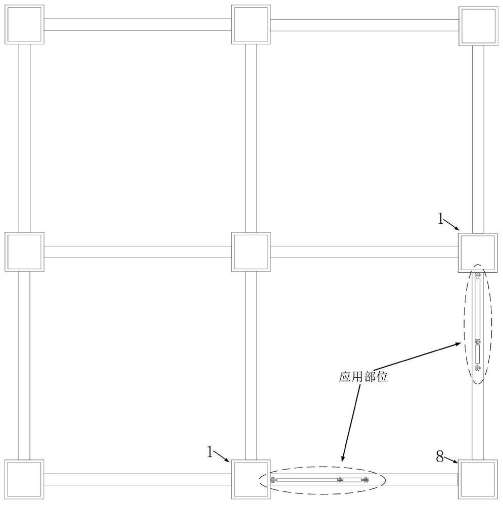
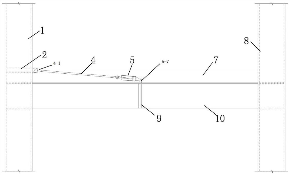
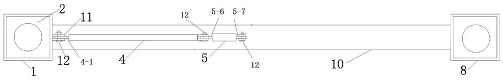
[0025] An anti-progressive collapse linkage mechanism suitable for steel-concrete composite structures, applied to the concrete-filled steel pipe column-steel beam scene, including convex corner columns (8), steel-filled concrete side columns (1), steel beams (10), and concrete floors ( 7), it is characterized in that: the rod-type hydraulic linkage mechanism includes a pull rod, an internal resistance hydraulic damper, several pin shafts, and several pin seats, wherein:

[0026] The tie rod (4) and the hydraulic damper (5) are connected in series through nodes, the damper is arranged flush with the axial center line of the tie rod, one end of which is connected to the column by a node, and the other end is connected to the steel beam (10) by a node, and the damping The full length of the device is buried in the concrete floor (7).

[0027] Further, each connection node is realized by a pin seat and a pin shaft mechanism. Further, the three nodes are arranged on the steel bea...


PUM


Abstract

The invention provides a rod type hydraulic linkage mechanism suitable for resisting progressive collapse of a steel-concrete combined structure. The rod type hydraulic linkage mechanism comprises a pull rod, an internal resistance type hydraulic damper, pin shafts and pin seats, wherein the pin seats are correspondingly mounted at the upper flange positions of a steel pipe-concrete column and a steel beam; one end of the pull rod and one end of the hydraulic damper are correspondingly connected with the pin seats on the steel pipe-concrete column and the steel beam through the pin shafts; and the other end of the pull rod and the other end of the hydraulic damper are connected through the pin shafts. The rod type hydraulic linkage mechanism is mainly applied to the position of a convex corner column of the steel-concrete combined structure, and aims to provide a standby force transmission path for resisting progressive collapse of the convex corner column, so that the situation that the structure continuously collapses after the convex corner column loses efficacy under the action of accidents (such as collision and explosion) is prevented. The rod type hydraulic linkage mechanism is simple in structure, convenient to construct and mount and high in reliability, does not affect normal use of the structure, and is suitable for being applied to the steel-concrete combined structure.

Description

technical field [0001] The application belongs to the field of steel-concrete composite structures, and relates to an anti-continuous collapse mechanism. Background technique [0002] Due to its advantages in stiffness and bearing capacity, steel-concrete composite structures are widely used in building structures, especially long-span, heavy-duty structures and high-rise buildings. However, because the current building design codes do not consider the effects of accidents (such as explosions, impacts, etc.) on structures, a large number of existing and newly built composite structures cannot meet the requirements of progressive collapse resistance. [0003] Among them, after the concrete-filled steel tube convex corner column in the composite structure fails under the action of an accident, the steel beams connected to it cannot provide an additional effective anti-collapse force transmission path, which is particularly likely to lead to continuous collapse of the structure...

Claims


Application Information

Patent Timeline
Patent Type & Authority Applications(China)
IPC IPC(8): E04B1/30E04B1/58E04B1/98E04B5/43E04G23/02E04H9/02
CPCE04B1/30E04B1/185E04B1/98E04B5/43E04G23/0218E04H9/021E04H9/027
Inventor 孔庆钊李杨袁程
Owner TONGJI UNIV
Why Eureka
Try Eureka