Fan and guide structure thereof

A fan and airflow technology, which is applied in the field of fans and their guide structures, can solve the problems of high noise, low air volume, and low efficiency, and achieve the effects of protecting circuits, large air volume, and saving space

Active Publication Date: 2010-09-15
DELTA ELECTRONICS INC
View PDF0 Cites 4 Cited by
  • Summary
  • Abstract
  • Description
  • Claims
  • Application Information

AI Technical Summary

Problems solved by technology

[0004] Compared with the axial flow fan, although the centrifugal fan can achieve the purpose of changing the air outlet direction, it has disadvantages such as low efficiency, low air volume, and high noise; moreover, if the fan is miniaturized and simplified Under the premise of multi-functional design, how to provide more functions under the original functions of the fan frame is also the place where the inventor is committed to researching the patent of the present invention

Method used


Image

  • Fan and guide structure thereof
  • Fan and guide structure thereof
  • Fan and guide structure thereof

Examples


Embodiment Construction

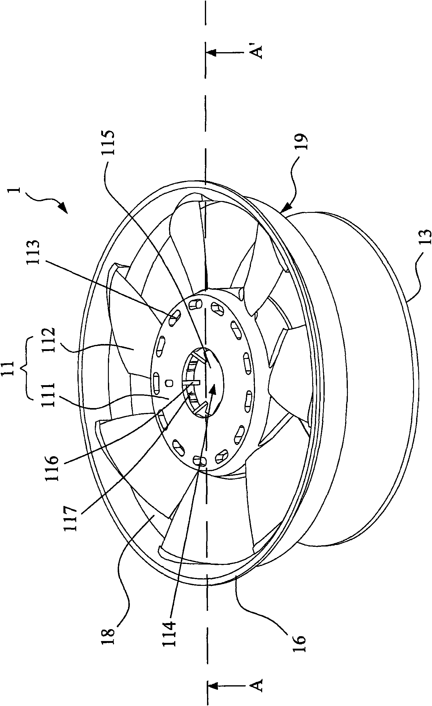
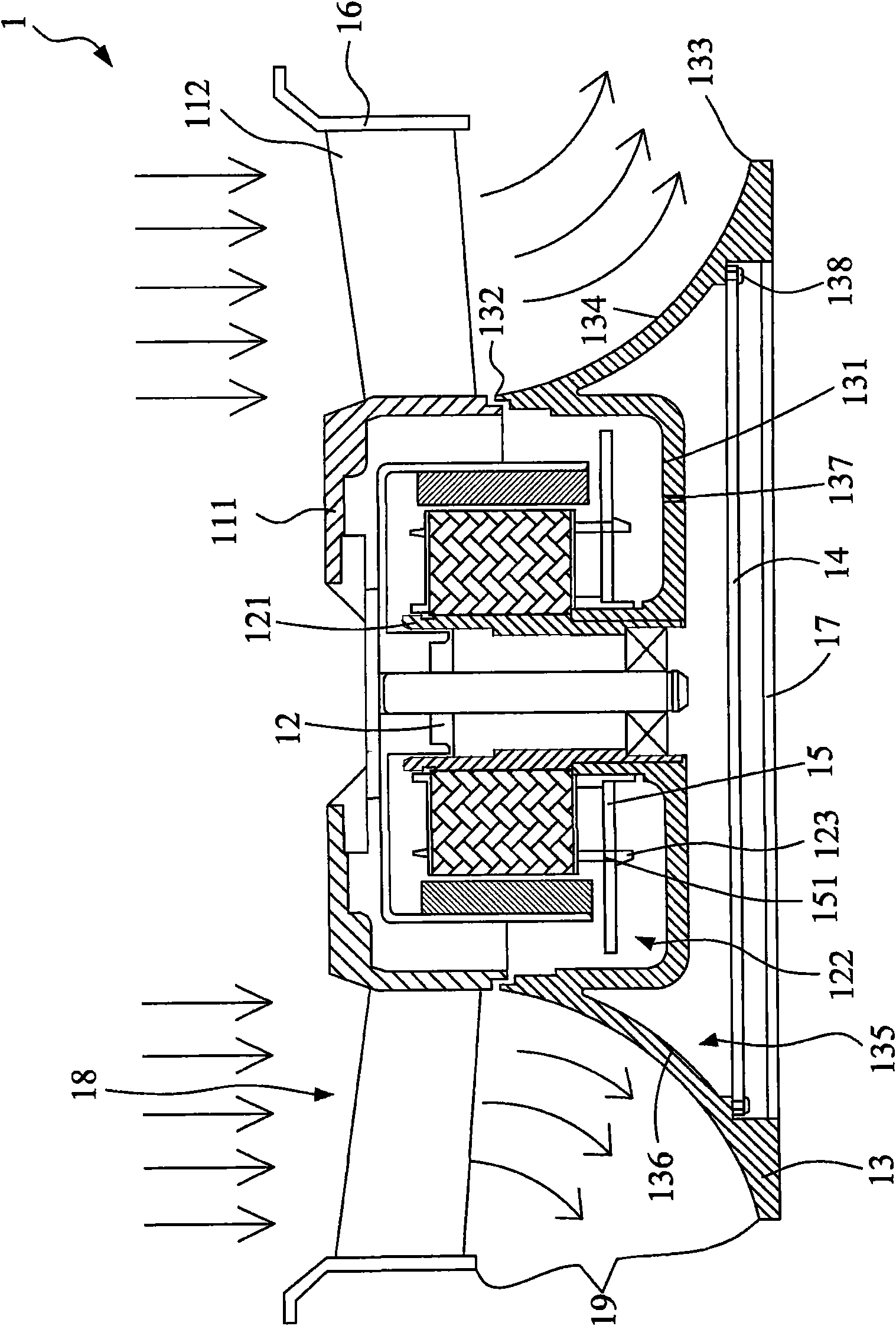
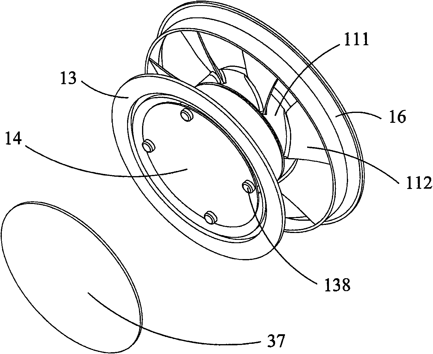
[0029] Please also refer to figure 1 and image 3 As shown, the fan 1 of the present invention can be an axial fan, and includes an impeller 11, a motor 12, a flow guide structure 13, a first circuit device 14, a second circuit device 15, and a guide ring 16. And a cover 17.

[0030] The impeller 11 has a hub 111 and a plurality of fan blades 112. The fan blades 112 are arranged on the outer ring surface of the hub 111, and the motor 12 is connected with the impeller 11 to drive the impeller 11 to rotate. Furthermore, the upper surface of the hub 111 has a plurality of balance holes 113. When the impeller 11 of the fan 1 is unbalanced, the balance hole 113 can be filled with appropriate balance materials according to the shaking state of the impeller 11 to make the fan The impeller 11 of 1 can rotate in a balanced manner without shaking.

[0031] In addition, the center of the hub 111 of the fan 1 has an air inlet groove 114. The inner wall of the air inlet groove 114 is hollowed...


PUM


Abstract

The invention discloses a fan and a guide structure thereof. The fan comprises a guide structure, an impeller and a motor, wherein the external diameter of the guide structure gradually expands to the bottom of the guide structure from the top of the guide structure. When the impeller rotates, airflow flows in from an air intake, flows along the outer ring surface of the guide structure and flowsout from an air outlet, and the direction from which the airflow flows out from the air outlet is different from the direction from which the airflow flows in from the air intake. In addition, the guide structure is provided with a first space in which external circuits can be arranged.

Description

Technical field [0001] The present invention relates to a fan, and more particularly to a fan and its flow guiding structure which can change the air flow direction and can accommodate external circuits or devices. Background technique [0002] With the continuous improvement of the performance of electronic devices, the heat dissipation device or heat dissipation system has become one of the indispensable equipment in the current electronic devices, because if the heat generated by the electronic device is not properly dissipated, the performance will deteriorate at the slightest. It will cause the electronic device to burn out. The heat sink is even more important for microelectronic components (such as integrated circuits, ICs), because with the increase in integration and the progress of packaging technology, the area of ​​integrated circuits is continuously reduced, and the heat energy accumulated per unit area It is also relatively higher, so heat dissipation devices with ...

Claims


Application Information

Patent Timeline
Patent Type & Authority Applications(China)
IPC IPC(8): F04D25/08F04D29/32H05K7/20
Inventor 许家铭张楯成林丽真
Owner DELTA ELECTRONICS INC
Why Eureka
Try Eureka