
Automatic control device for forced draught fan

A technology of automatic control devices and blowers, applied in pump control, machine/engine, mechanical equipment, etc., can solve problems such as potential safety hazards, enterprise losses, increased repair and maintenance costs, etc.

Inactive Publication Date: 2010-09-15
谭程程 +1
View PDF0 Cites 4 Cited by
  • Summary
  • Abstract
  • Description
  • Claims
  • Application Information

AI Technical Summary

Problems solved by technology

Therefore, the control process of the original compressor only has the functions of "manual" start and stop and "manual" loading and unloading. Sudden power failure will cause high-pressure gas to hard impact on the machine body, couplings, motors and other equipment, reduce the service life of the machine, increase repair and maintenance costs, and even lead to production stoppage, causing great losses to the enterprise
In addition, in terms of compressed gas overpressure protection, the original machine uses a safety valve as a single overpressure protection component. Once the pneumatic control circuit fails, it will cause major safety hazards

Method used


Image

  • Automatic control device for forced draught fan
  • Automatic control device for forced draught fan
  • Automatic control device for forced draught fan

Examples


Embodiment Construction

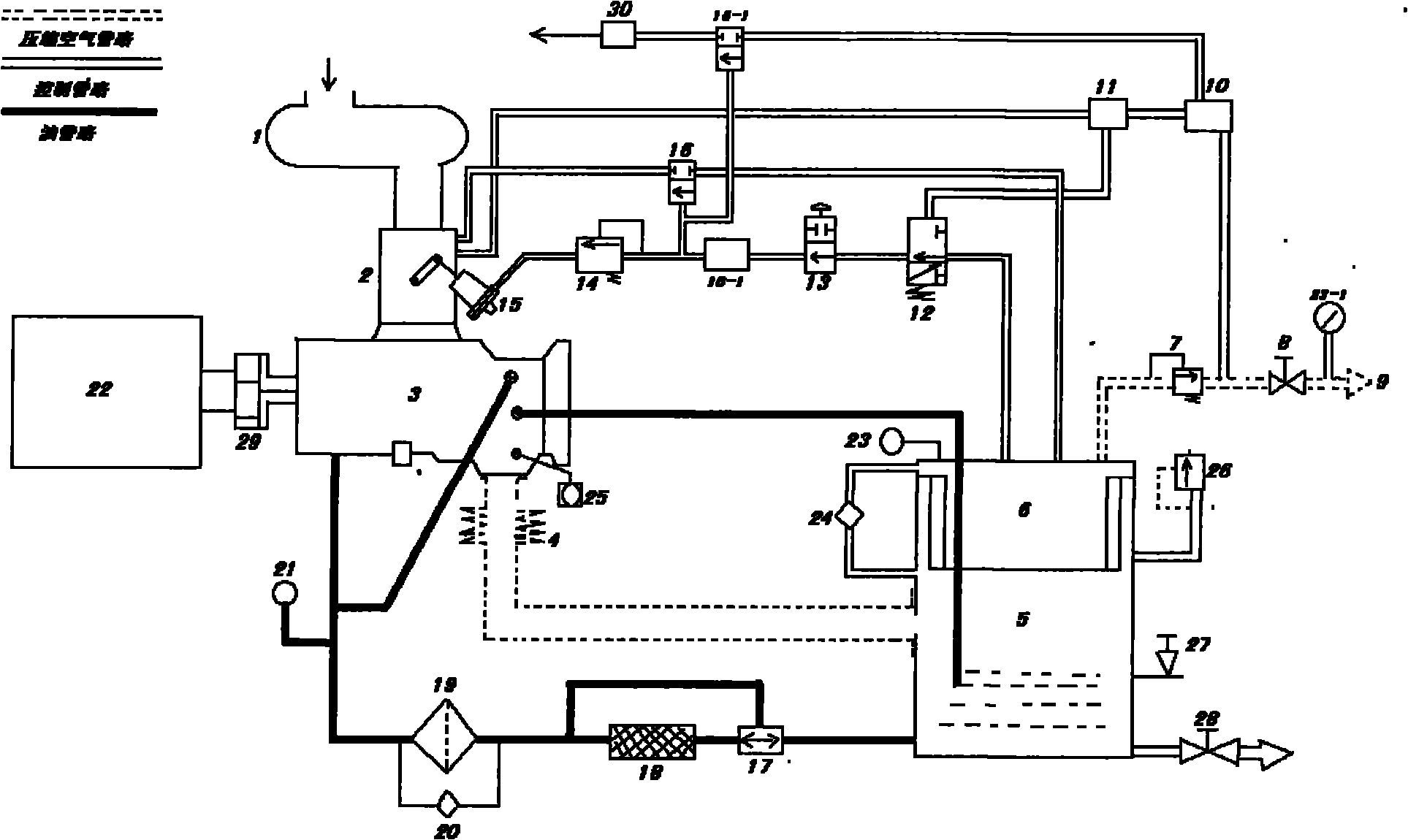
[0041] (1) Basic principle: press the start control button of the compressor, turn on the compressor, and load it manually. During the process of gradually increasing the pressure of the compressor, turn the "manual / automatic" switch of the electrical control of the device to the "automatic" position. When the outlet pressure of the exhaust pipe of the compressor reaches the artificially set "high" pressure value, the pneumatic switch of this device will connect the motor to control the electric stop circuit of the magnetic starter, and the device will automatically stop after a delay. When the pressure of the compressed air system gradually drops to the artificially set self-starting "low" pressure value, after the conversion of the device, the fan is automatically turned on, and the automatic loading is completed, so that the fan operates normally and the system pressure continues to rise. When the system pressure rises and reaches the artificially set "high" pressure value, ...


PUM


Abstract

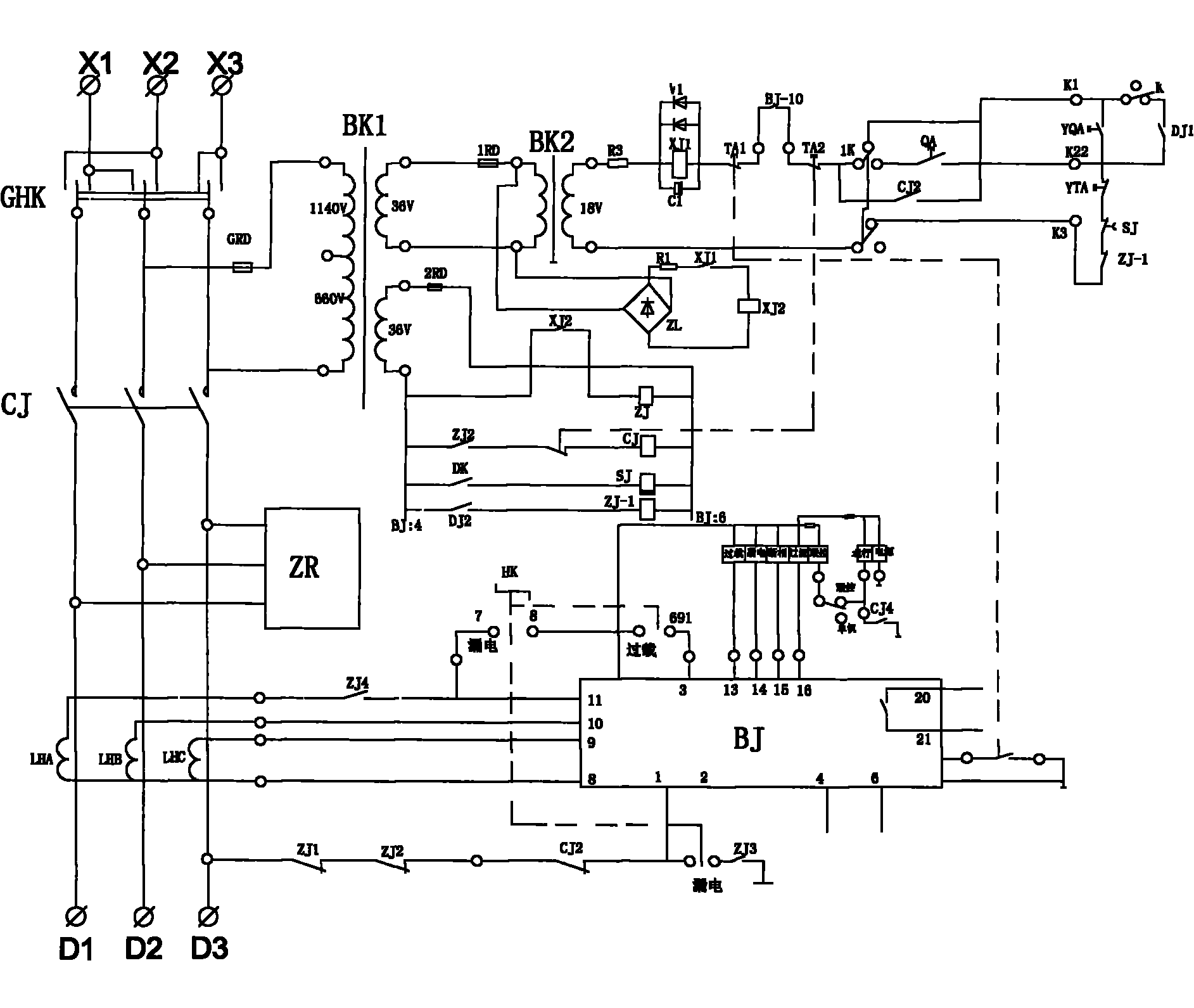
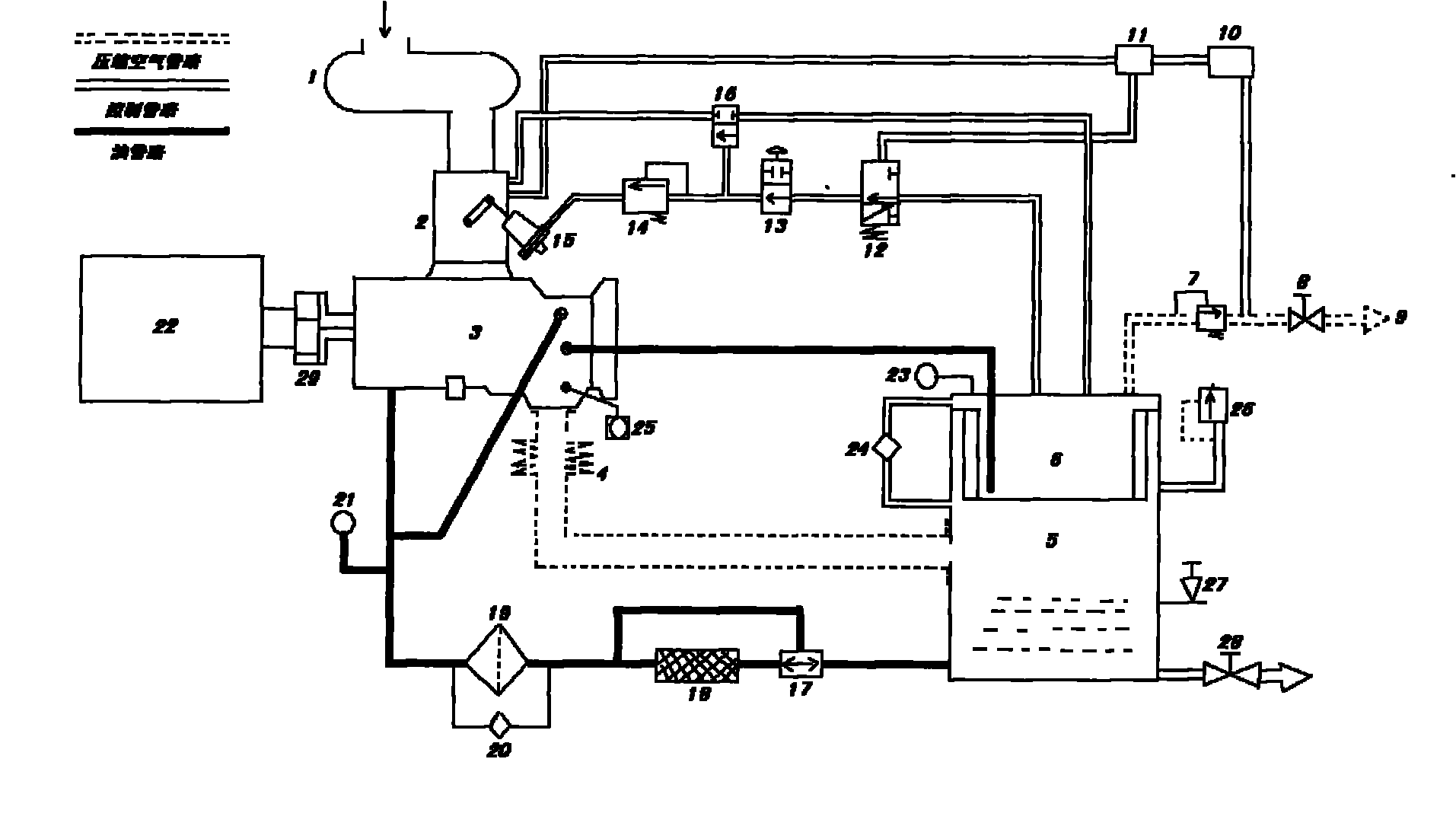
The invention discloses a mechanical control device for automatically controlling a forced draught fan in the soft environment. A pilot valve, a discharge valve, a pneumatic switch, a pneumatic time delay valve and a pneumatic control valve are added into a pneumatic control loop which is formed by sequentially connecting a forced draught fan oil vapor tank, the pneumatic control valve, a hand operated valve, the discharge valve, an inverse proportion valve, a butterfly valve control cylinder, the pilot valve, a shuttle valve, a pressure maintaining valve and a ball valve pneumatic element; an explosion-proof electric contact pressure gauge is arranged in an electric pneumatic control loop; a time relay and an intermediate relay are connected in parallel with a magnetic starter control loop; a pressure gauge on the forced draught fan oil vapor tank is replaced by the explosion-proof electric contact pressure gauge; and a forced draught fan remote-control staring button loop is connected in series with the mechanical automatic control device of a toggle switch. When a pressure of a compressed air system is low, the forced draught fan automatically starts; and when the pressure of the compressed air system is high, the forced draught fan automatically delays and performs soft stop, and the system pressure is kept in a certain range. The automatic control device realizes automatic control, and automatic delay buffer stop, so that impact of high pressure gas on mechanical devices, such as an engine body and the like is relieved, potential safety hazard caused by overpressure of compressed air is removed, automatic start and automatic delay loading, automatic unloading, and automatic delay buffer stop are realized, and the whole procedure has the functions of automatic control and protection. The automatic control device for the forced draught fan has the advantages of simple structure, easy operation, convenient maintenance, safety, reliability and the like.

Description

Technical field [0001] The invention relates to the automatic control technology of the compressor, especially by adding a small amount of components to the existing electrical control circuit and pneumatic control pipeline, the automatic control of the compressor in a soft environment can be realized, and the main compression parts such as the cylinder can be effectively reduced, Air control components, motors and couplings are damaged, and the modification investment is small, with high cost performance. Background technique [0002] At present, the original machine of the SM series compressor produced by Fusheng Company controls the magnetic starter of the compressor by "manually" operating the remote control button to realize start and stop; and then "manually" operates the manual valve installed on the pneumatic control circuit , to open or close the butterfly valve at the air inlet of the cylinder to realize loading and unloading of the compressor. Therefore, the cont...

Claims


Application Information

Patent Timeline
IPC IPC(8): F04D27/00
Inventor 谭程程张胜利
Owner 谭程程
Learn More