Structure for locking wheel locking nut and drive shaft

A drive shaft and dead nut technology, applied in the direction of nuts, screws, bolts, etc., can solve the problems of damaging the brake 1 bearing, failing to meet the torque requirements of locked wheels and drive shafts, etc.

Inactive Publication Date: 2010-09-15
CHONGQING CHANGAN AUTOMOBILE CO LTD
View PDF6 Cites 1 Cited by
  • Summary
  • Abstract
  • Description
  • Claims
  • Application Information

AI Technical Summary

Problems solved by technology

[0003] At present, the locking method with cotter pin type is mostly used at home and abroad, see figure 1 and figure 2 , it must make the opening 5 of the cotter pin type lock nut 2 consistent with the shaft opening 6 on the drive shaft 4, so as to ensure that the cotter pin 3 passes through the installation hole smoothly, and ensuring their consistency requires high manufacturing accuracy , otherwise it will not meet the requirements of locked wheel and drive shaft torque after assembly, which may damage the bearing of brake 1

Method used


Image

  • Structure for locking wheel locking nut and drive shaft
  • Structure for locking wheel locking nut and drive shaft
  • Structure for locking wheel locking nut and drive shaft

Examples


Embodiment Construction

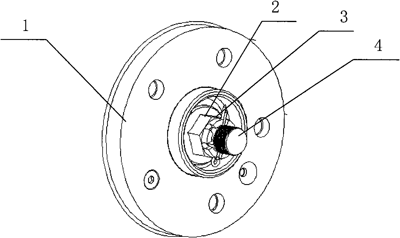
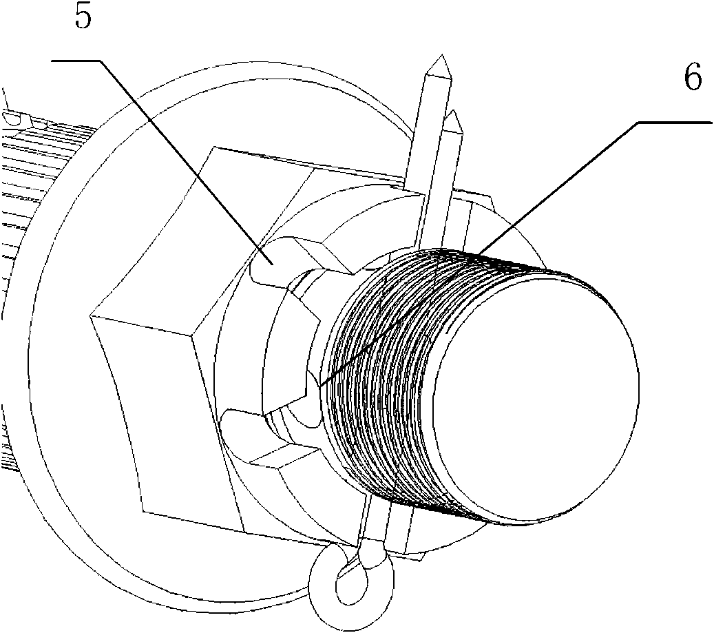
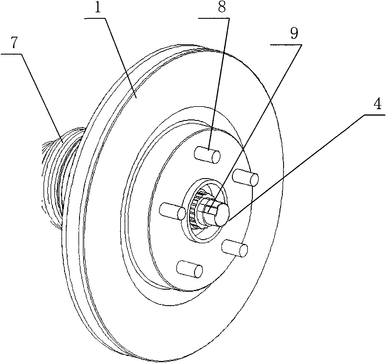
[0013] see Figure 5 The locking structure of the wheel lock nut and the drive shaft proposed by the present invention mainly improves the structure of the lock nut 9 . The outer peripheral surface of the wheel locknut is designed to be divided into three sections by three steps, the bottom section is a disc washer end 91, the middle section is a polygonal cylindrical body 92, and the upper section is a locking edge 93 . Correspondingly, the drive shaft 4 also needs to be improved a bit, and a section of inclined groove 41 is cut on the outer peripheral surface of the drive shaft 4 near the end.

[0014] see image 3 and Figure 4 , in the assembly process, assemble the lock nut 9 on the drive shaft 4, when the torque required for lock is reached, just knock down the lock nut edge 93 until it is in contact with the drive shaft 4 The chute 41 is close to each other, so that the knocked-off locking edge 93 cooperates with the chute 93 at the end of the drive shaft, so that t...


PUM


Abstract

The invention discloses a structure for locking a wheel locking nut and a drive shaft, comprising a wheel locking nut and a drive shaft. The outer circumferential surface of the wheel locking nut is divided into three sections by three steps, wherein the section of the most lower end is a disc gasket end, the middle section is a polygonal cylindrical main body, and the section of the upper end is a locking edge; the outer circumferential surface of drive shaft, which is near the end, is provided with a skewed slot; after the wheel locking nut is screwed down on the drive shaft, the locking edge is knocked until the wheel locking nut clings to the skewed slot, thereby locking the wheel locking nut and the drive shaft. The structure cancels a cotter pin, which solves the problem that the connection of the wheel and the drive shaft is not reliable. The locking nut of the structure has simple and easy processing and has reliable connection with the drive shaft. Compared with the traditional structure, the structure has more convenient assembly, and the required accuracy of locking and torsion is improved.

Description

technical field [0001] The invention relates to the technology of locking between an automobile wheel and a drive shaft. Background technique [0002] Front-wheel drive cars require a safety lock on the connection between the wheel and the drive shaft to prevent the connection between the wheel and the drive shaft, which will cause the car to lose power instantly and endanger the safety of the car. To solve this problem, the wheels must be firmly locked to the drive shaft. [0003] At present, the locking method with cotter pin type is mostly used at home and abroad, see figure 1 and figure 2 , it must make the opening 5 of the cotter pin type lock nut 2 consistent with the shaft opening 6 on the drive shaft 4, so as to ensure that the cotter pin 3 passes through the installation hole smoothly, and ensuring their consistency requires high manufacturing accuracy , otherwise it will not meet the torque requirements for locking the wheel and the drive shaft after assembly, ...

Claims


Application Information

Patent Timeline
Patent Type & Authority Applications(China)
IPC IPC(8): F16B39/02
Inventor 王志龙张晓龙蒋平叶宏璐芦岩
Owner CHONGQING CHANGAN AUTOMOBILE CO LTD
Why Eureka
Try Eureka