Temperature control device and method for laser display light source and laser display device
A technology of temperature control device and laser display, which is applied in the direction of temperature control, laser cooling device, laser parts, etc., can solve the problem of continuous working time and volume increase of the laser, so as to prolong the continuous working time and delay the temperature rise Speed, overcoming the effect of volume increase
- Summary
- Abstract
- Description
- Claims
- Application Information
AI Technical Summary
Problems solved by technology
Method used
Image

Examples
Embodiment 1
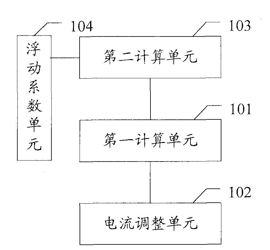
[0023] figure 1 Embodiment 1 of the present invention provides a temperature control device for a laser display light source. The temperature control device controls the current of the laser to achieve temperature control. Among them, the laser dissipates heat through the radiator, and there can be various connection relationships between the radiator and the laser, as long as the heat of the laser can be transferred to the radiator and dissipated by the radiator, for example, it can be used between the laser and the laser. A heat conduction device is provided between the radiators, and the heat conduction device is used to efficiently export the heat of the laser to the radiator.
[0024] Such as figure 1 As shown, the temperature control device in this embodiment includes: a first calculation unit 101 and a current adjustment unit 102 .
[0025] The first calculation unit 101 is used to calculate the difference between the current temperature of the radiator and the ambien...
Embodiment 2
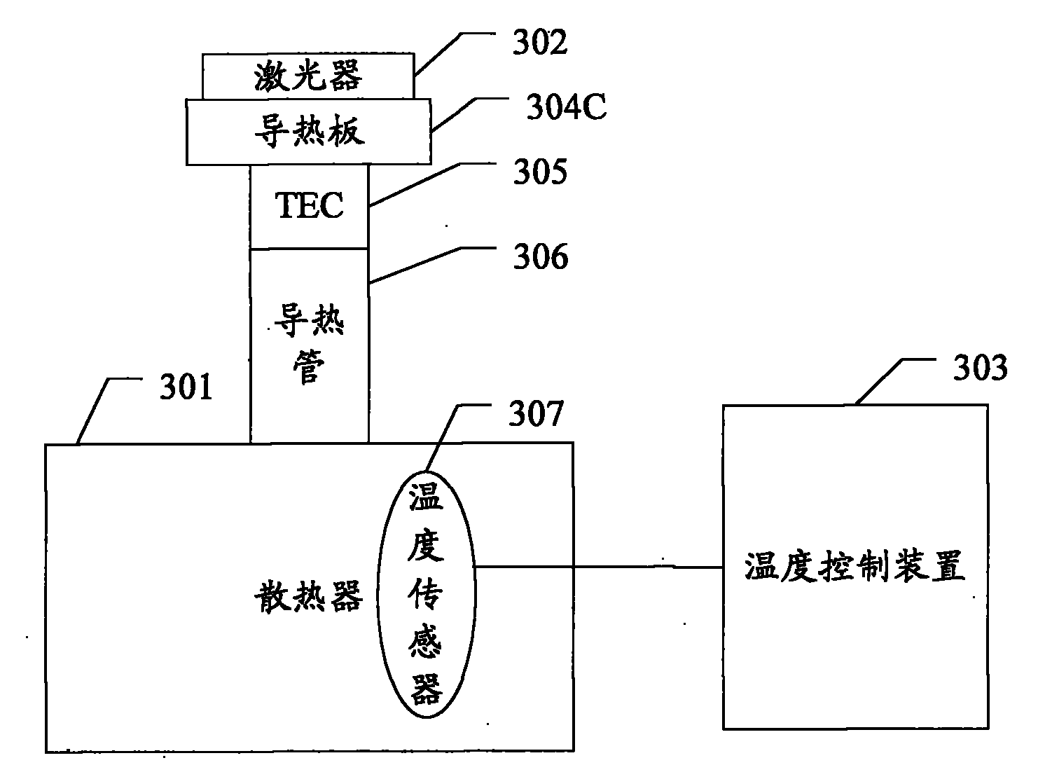
[0061] image 3 A schematic diagram of one form of the laser display device provided by this embodiment is shown. Such as image 3 As shown, the laser display device includes a heat sink 301 and a laser 302 that dissipates heat through the heat sink 301 . It should be noted that those skilled in the art should understand that the laser display device also includes devices such as an optical engine and a projection lens. image 3 is not shown in , and will not be repeated here.
[0062]The heat sink 301 and the laser 302 are preferably provided with a heat conduction device, and the laser 302 is connected to the heat sink 301 through the heat conduction device. image 3 In particular, the heat conduction device includes a heat conduction plate 304, a semiconductor cooler (TEC) 305 and a heat pipe 306 as an example, wherein the laser 302 is connected to the cold end of the semiconductor cooler 305 through the heat conduction plate 304, and one end of the heat conduction pipe ...
Embodiment 3
[0069] This embodiment correspondingly provides a method for controlling the temperature of a laser display light source, wherein the laser display light source includes a radiator and a laser that dissipates heat through the radiator. Such as Figure 5 As shown, the method includes the following steps:
[0070] Step S501: Calculate the difference between the current temperature of the radiator and the ambient temperature, and multiply the obtained difference by the current adjustment coefficient to obtain the current adjustment value;
[0071] Step S502: Decrease the current applied to the laser, and the current reduction amount is equal to the obtained current adjustment value.
[0072] Preferably, step S500 is also performed before step S501: calculate the current adjustment coefficient, the current adjustment coefficient is the maximum operating temperature difference of the radiator divided by the thermal resistance between the laser and the radiator, and then divided by...
PUM
 Abstract
Description
Claims
Application Information
 - R&D
- Intellectual Property
- Life Sciences
- Materials
- Tech Scout
- Unparalleled Data Quality
- Higher Quality Content
- 60% Fewer Hallucinations
Browse by: Latest US Patents, China's latest patents, Technical Efficacy Thesaurus, Application Domain, Technology Topic, Popular Technical Reports.
© 2025 PatSnap. All rights reserved.Legal|Privacy policy|Modern Slavery Act Transparency Statement|Sitemap|About US| Contact US: help@patsnap.com