A Carbon Brush Mechanism Based on Motor Collector Ring

A collector ring and carbon brush machine technology, which is applied in the direction of electric components, electromechanical devices, electrical components, etc., can solve the problem of the non-stop working time of carbon brush motors with small frictional carbon deposits, the temperature of carbon brushes or collector rings Problems such as rising, carbon brush wear and carbon deposition, to achieve the effect of prolonging the duration, shortening the cycle of carbon deposition, and reducing wear

Active Publication Date: 2021-11-30
合肥皖化电机技术开发有限责任公司
View PDF14 Cites 0 Cited by
  • Summary
  • Abstract
  • Description
  • Claims
  • Application Information

AI Technical Summary

Problems solved by technology

[0005] The invention provides a carbon brush mechanism based on the collector ring of the motor, which has the advantages of small friction between the carbon brush and the collector ring, shortens the cycle of carbon deposition on the carbon brush, prolongs the service life of the carbon brush, slows down the The advantages of increasing the temperature of the carbon brush or the collector ring and prolonging the working time of the motor without stopping, solve the problem of sliding friction contact between the existing carbon brush structure and the collector ring, which leads to The friction between the carbon brush and the collector ring is relatively large, and the wear and carbon deposition of the carbon brush are more serious, and in the process of use, it is very easy to cause local ignition due to poor contact, which greatly affects the The service life of the carbon brush, and because of the large friction between the carbon brush and the collector ring, the temperature of the carbon brush or the collector ring will rise rapidly when the motor is used for a long time, and it needs to be shut down The problem of not being able to use it for a long time without stopping the machine due to cooling treatment

Method used


Image

  • A Carbon Brush Mechanism Based on Motor Collector Ring
  • A Carbon Brush Mechanism Based on Motor Collector Ring
  • A Carbon Brush Mechanism Based on Motor Collector Ring

Examples


Embodiment Construction

[0022] The following will clearly and completely describe the technical solutions in the embodiments of the present invention with reference to the accompanying drawings in the embodiments of the present invention. Obviously, the described embodiments are only some, not all, embodiments of the present invention. Based on the embodiments of the present invention, all other embodiments obtained by persons of ordinary skill in the art without making creative efforts belong to the protection scope of the present invention.

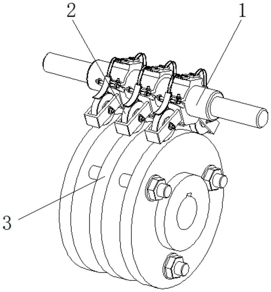
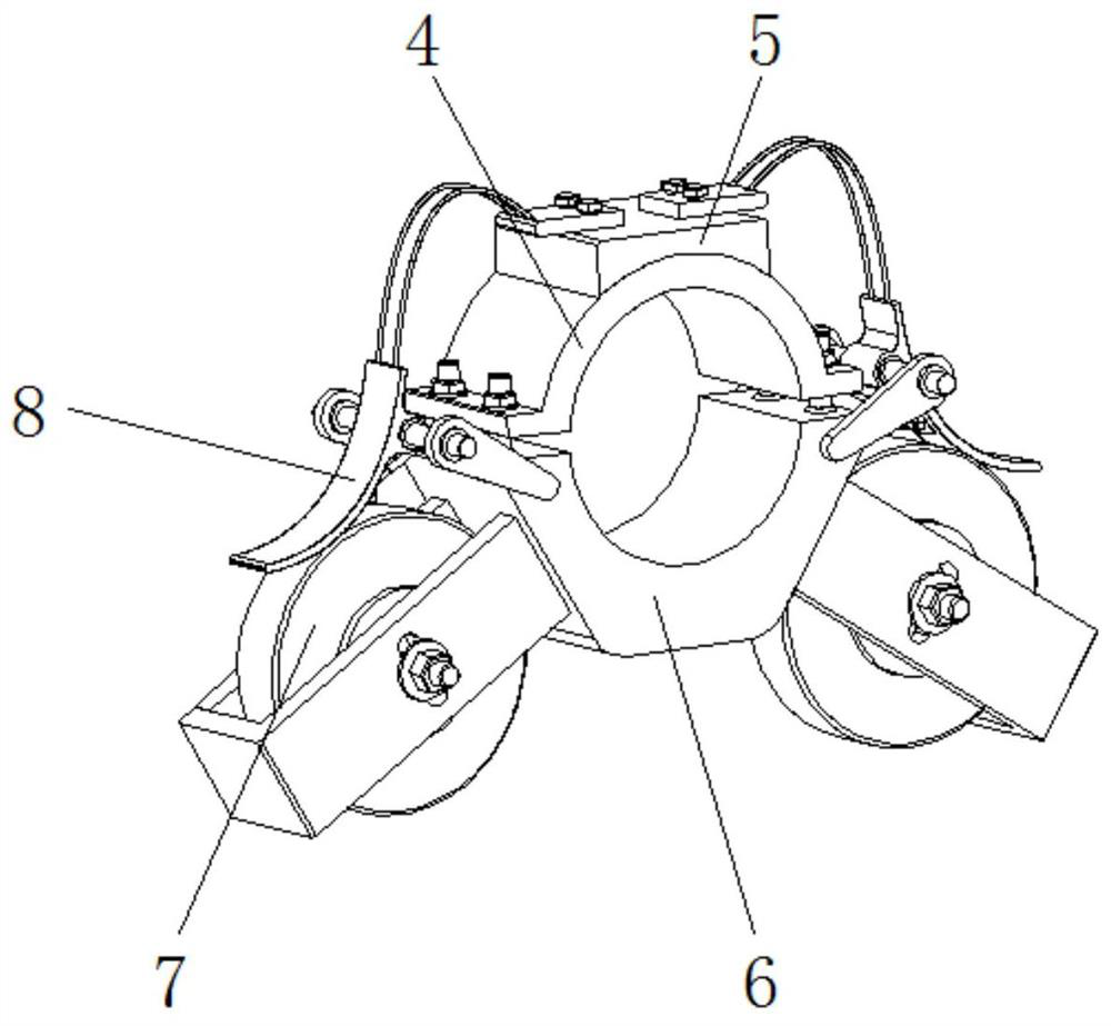
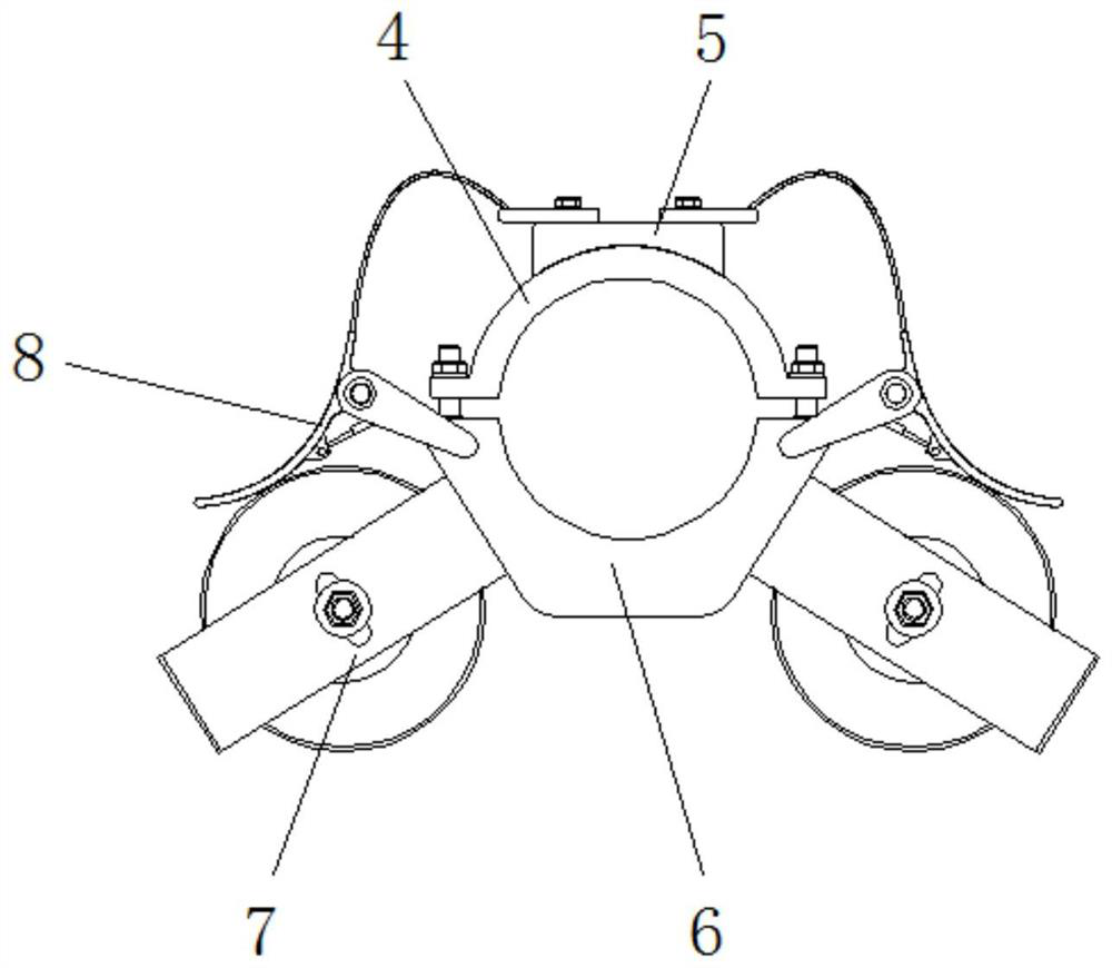
[0023] see Figure 1-5 , a carbon brush mechanism based on a motor collector ring, including a carbon brush frame 1, a carbon brush mechanism 2 is fixedly installed in the middle of the outer surface of the carbon brush frame 1, and a collector ring 3 is provided at the bottom of the carbon brush frame 1, and carbon The outer surface of the brush mechanism 2 is in contact with the outer wall of the collector ring 3. The carbon brush mechanism 2 is divided into...


PUM


Abstract

The invention relates to the technical field of motor components, and discloses a carbon brush mechanism based on a motor collector ring, including a carbon brush frame, and a carbon brush mechanism is fixedly installed in the middle of the outer surface of the carbon brush frame, and the carbon brush mechanism is divided into two parts: It is an upper bracket and a lower bracket. The upper bracket and the lower bracket are fixed on the outer wall of the carbon brush frame through a screw. The top of the upper bracket is fixedly installed with a terminal. The carbon brush body is fixedly installed on both sides, and the bottom end of the outer wall of the carbon brush is in contact with the outer wall of the collector ring. The carbon brush mechanism based on the motor collector ring, for the contact connecting plate external arc structure and the setting of the contact position with the carbon brush body, makes one end of the contact connecting plate always maintain a warped state when it contacts the carbon brush body , to prevent its corners from scratching the surface of the carbon brush body, and further improve the stability of the contact between the contact plate and the carbon brush body.

Description

technical field [0001] The invention relates to the technical field of motor components, in particular to a carbon brush mechanism based on a collector ring of a motor. Background technique [0002] The motor is a device that uses the stator winding to generate a rotating magnetic field and acts on the rotor to form a dynamic rotating torque. It is mainly used to convert electrical energy into mechanical energy, and the collector ring and carbon brush are important components of the motor. The device that transmits energy and signals between the fixed part and the rotating part of the motor, and the carbon brush, as a sliding contact part mainly made of carbon, is prone to wear and tear and requires regular maintenance and replacement. [0003] However, the existing carbon brush structure and the collector ring are in a sliding friction contact mode, which leads to a large friction force between the carbon brush and the collector ring, and the wear and carbon deposition of t...

Claims


Application Information

Patent Timeline
Patent Type & Authority Patents(China)
IPC IPC(8): H02K5/14H02K13/00H02K13/10
CPCH02K5/141H02K13/003H02K13/10
Inventor 李功向
Owner 合肥皖化电机技术开发有限责任公司
Why Eureka
Try Eureka