Shielded wire with lead wire and treatment process thereof

A technology of shielded wires and lead wires, which is applied in the direction of twisted/quad-stranded cables, line/collector parts, multi-core cable end parts, etc., which can solve the short circuit of wires and require high operating skills , high processing costs and other issues, to achieve the effect of reducing manufacturing costs

Active Publication Date: 2010-09-15
ZHUZHOU CSR TIMES ELECTRIC CO LTD
View PDF3 Cites 16 Cited by
  • Summary
  • Abstract
  • Description
  • Claims
  • Application Information

AI Technical Summary

Benefits of technology

This patented technology allows for better protection against electrical interference from external sources such as radio waves without adding extra layers on top. Additionally it prevents damage caused by heat during the bonding process due to excessive pressure applied over time.

Problems solved by technology

In this patented technical problem addressed in the patents text relates to improving the reliability and efficiency of electricity transmitting systems due to poor connections caused from faulty connectors during power supply lines. Current solutions involve either adding extra components like conductive tape layers around each connector or applying an external force to separate them before joining them. However these techniques have limitations including low precision, potential damage to sensitive equipment, increased labor costs associated with handling heavy materials, and difficulty in attaching leads without damaging their integrity.

Method used


Image

  • Shielded wire with lead wire and treatment process thereof
  • Shielded wire with lead wire and treatment process thereof
  • Shielded wire with lead wire and treatment process thereof

Examples


Embodiment Construction

[0028] The following will clearly and completely describe the technical solutions in the embodiments of the present invention with reference to the accompanying drawings in the embodiments of the present invention. Obviously, the described embodiments are only part of the embodiments of the present invention, not all of them. Based on the embodiments of the present invention, all other embodiments obtained by persons of ordinary skill in the art without creative efforts fall within the protection scope of the present invention.

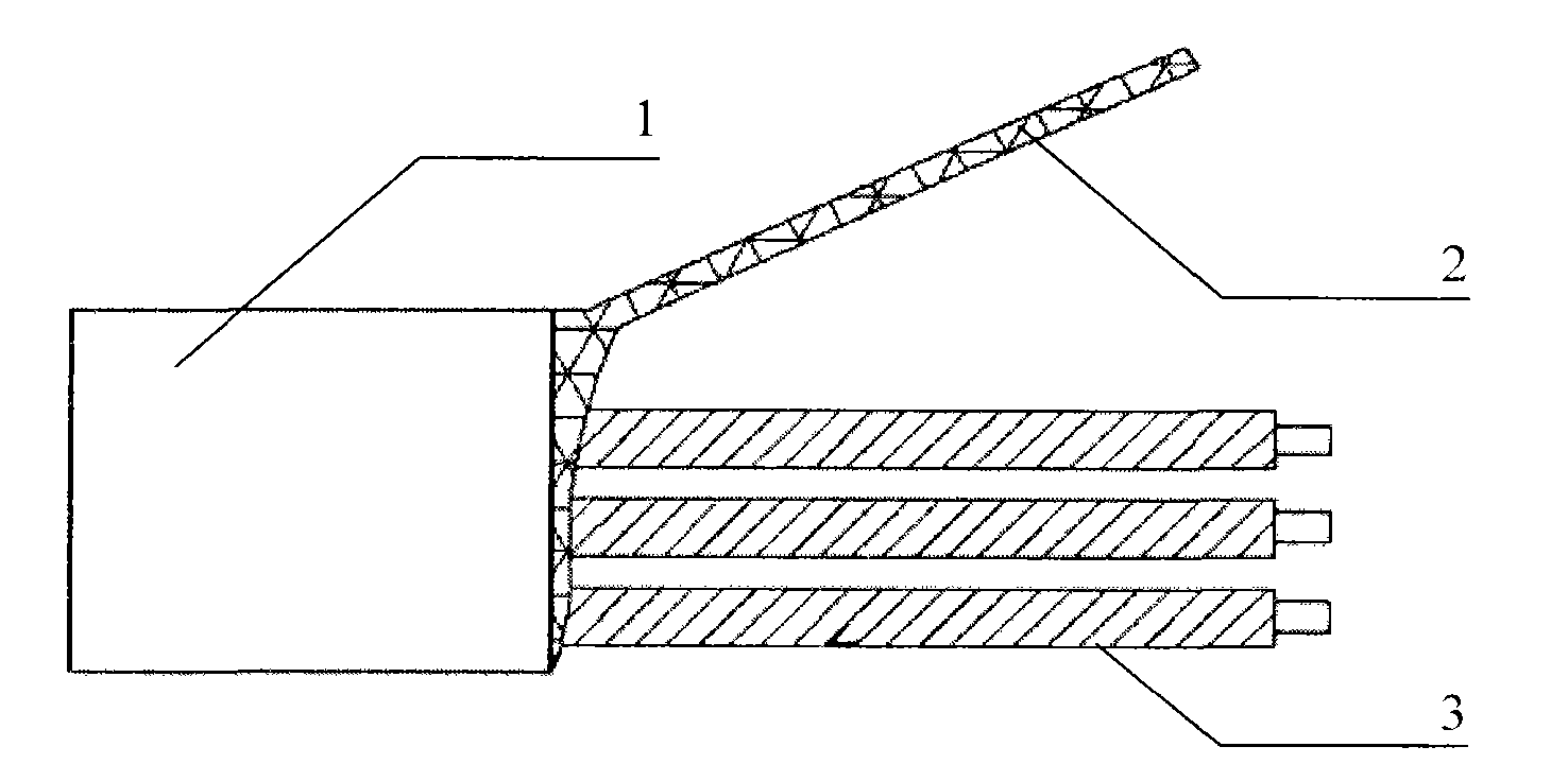
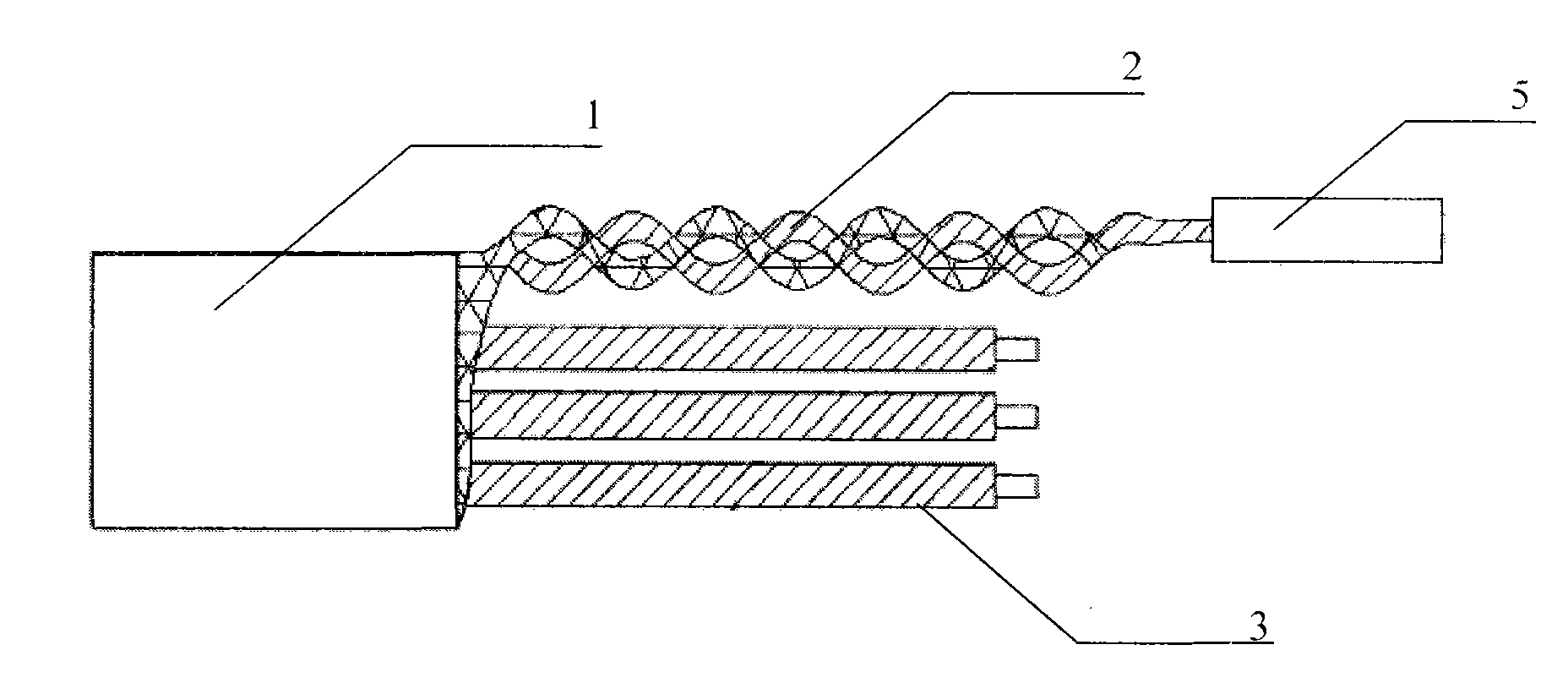
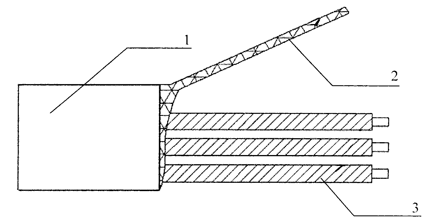
[0029] The present invention calculates the size of the shielding layer of the shielding wire, and then protects the shielding layer to make it reach the performance of the lead-out wire, thereby directly leading out the grounding method instead of the lead-out wire. As a specific embodiment of the present invention, such as Figure 8 and Figure 9 As shown, a shielded wire with leads includes a jacket 1, a shielding layer 2 and a shielded core wire ...


PUM


Abstract

The invention discloses a shielded wire with a lead wire and a treatment process thereof. The shielded wire comprises a jacket, a shielding layer and a shielded wire core wire, wherein the shielding layer is a netlike woven lead, the shielding layer is arranged outside the shielded wire core wire, the jacket wraps the shielding layer and the shielded wire core wire, the shielding layer is woven into a linear leading-out wire, a protection sleeve wraps the shielding layer leading-out wire, and the protection sleeve is a heat-shrinkable sleeve. The treatment process comprises the following steps of: calculating the section area of the shielding layer of the shielded wire; selecting the protection sleeve with corresponding performance according to the size of the shielding layer and the insulation, voltage resistance, length and using environment of the leading-out wire; peeling the jacket of the shielded wire, and weaving the shielding layer into the leading-out wire; shearing and trimming the tail of the shielding layer of the shielded wire; and blowing the heat-shrinkable sleeve to tightly wrap the shielding layer, wherein the protection sleeve adopts the heat-shrinkable sleeve. The shielded wire effectively avoids the problem that burrs puncture the lead to cause short circuit after the shielding layer is crimped or welded, and the leading wire of the connected shielding layer is not easy to drop under a high-temperature environment so as to reduce the manufacturing cost and the requirement on the operation process.

Description


Claims


Application Information

Patent Timeline
Owner ZHUZHOU CSR TIMES ELECTRIC CO LTD
Why Eureka
Try Eureka