
Disc permanent-magnet synchronous multi-combination power DC motor group

A permanent magnet synchronous, combined power technology, applied in synchronous motors with static armatures and rotating magnets, electric components, magnetic circuit rotating parts, etc., can solve the problem of shortened vehicle mileage and shortened battery life. , the speed-up time of the whole vehicle is prolonged, etc., to achieve the effect of fast start-up speed-up time, reduced power consumption, and shortened discharge time

Inactive Publication Date: 2010-09-15
SUZHOU BOZUN SCI & TECH
View PDF5 Cites 5 Cited by
  • Summary
  • Abstract
  • Description
  • Claims
  • Application Information

AI Technical Summary

Problems solved by technology

If the starting current of 300 volts or more than 1000 amps cannot be guaranteed, the speed-up time of the vehicle will be prolonged, resulting in long-term high-current discharge of the battery. Due to the capacity limitation of the battery, the continuation mileage of the vehicle will be shortened.
At present, the speed of 5kw column motor on the market is 80 kilometers per hour, the starting current is 100 amps, and the full speed driving current is 70 amps, and it is not in the best condition.
[0004] 2) Long-term high-current discharge will cause damage to the battery, shorten the service life of the battery, and increase the operating cost
[0005] 3) The efficiency of the traditional column motor itself is low, so the power must be increased, resulting in increased volume, heavy weight, greatly increased raw material costs, and increased relative cost

Method used


Image

  • Disc permanent-magnet synchronous multi-combination power DC motor group
  • Disc permanent-magnet synchronous multi-combination power DC motor group
  • Disc permanent-magnet synchronous multi-combination power DC motor group

Examples


Embodiment Construction

[0024] Preferred embodiments of the present invention will be described in detail below in conjunction with the accompanying drawings.

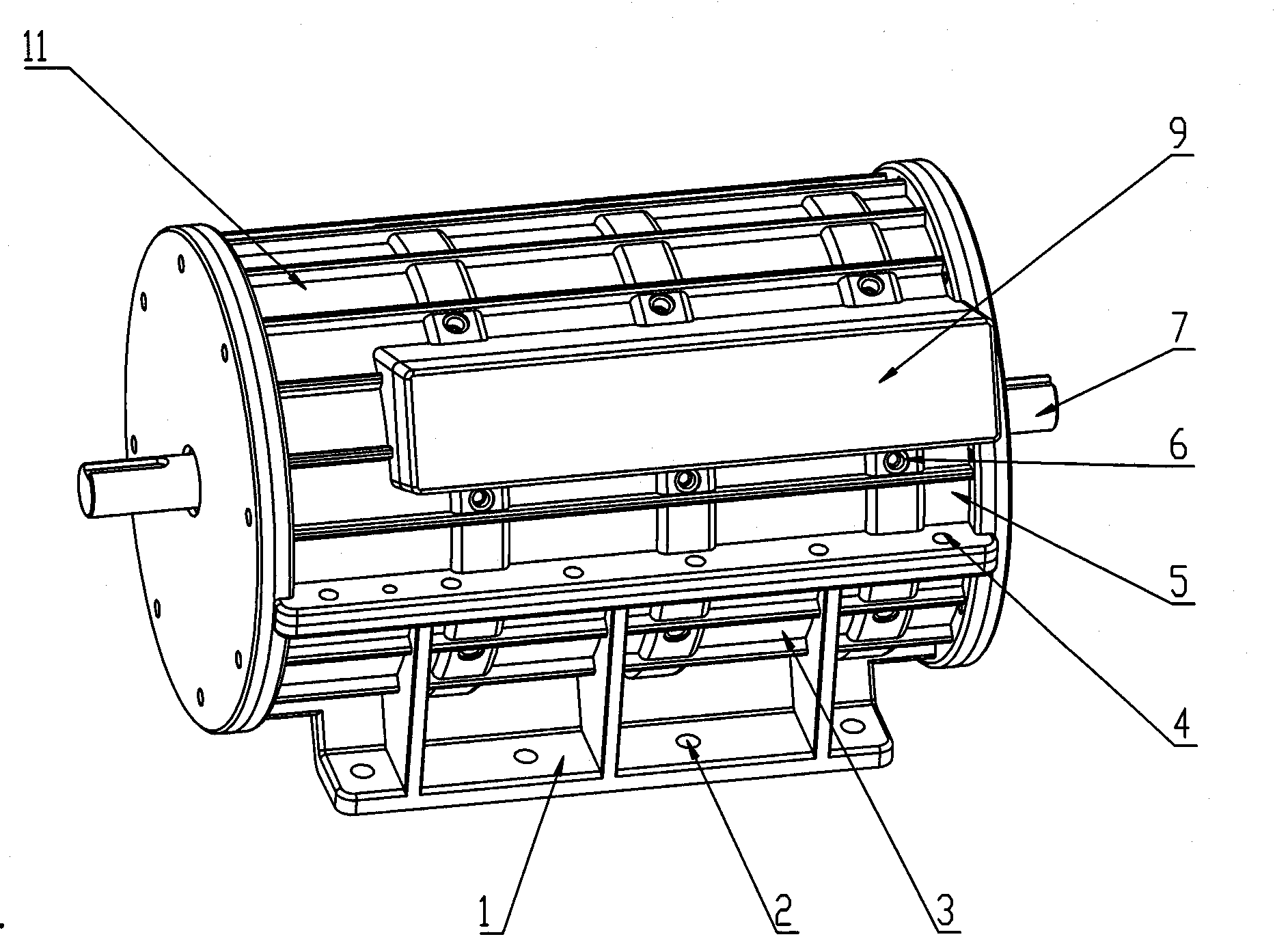
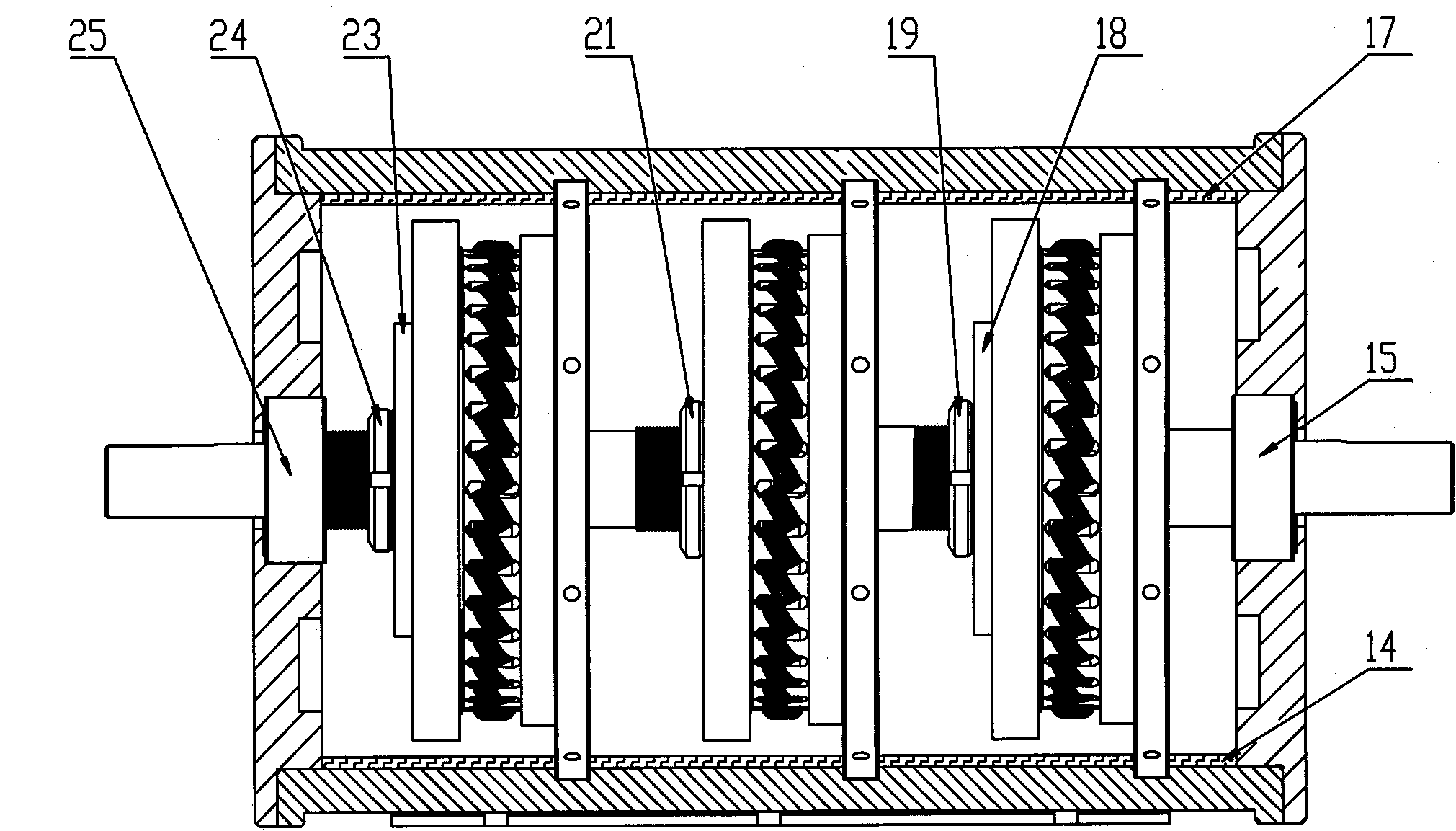
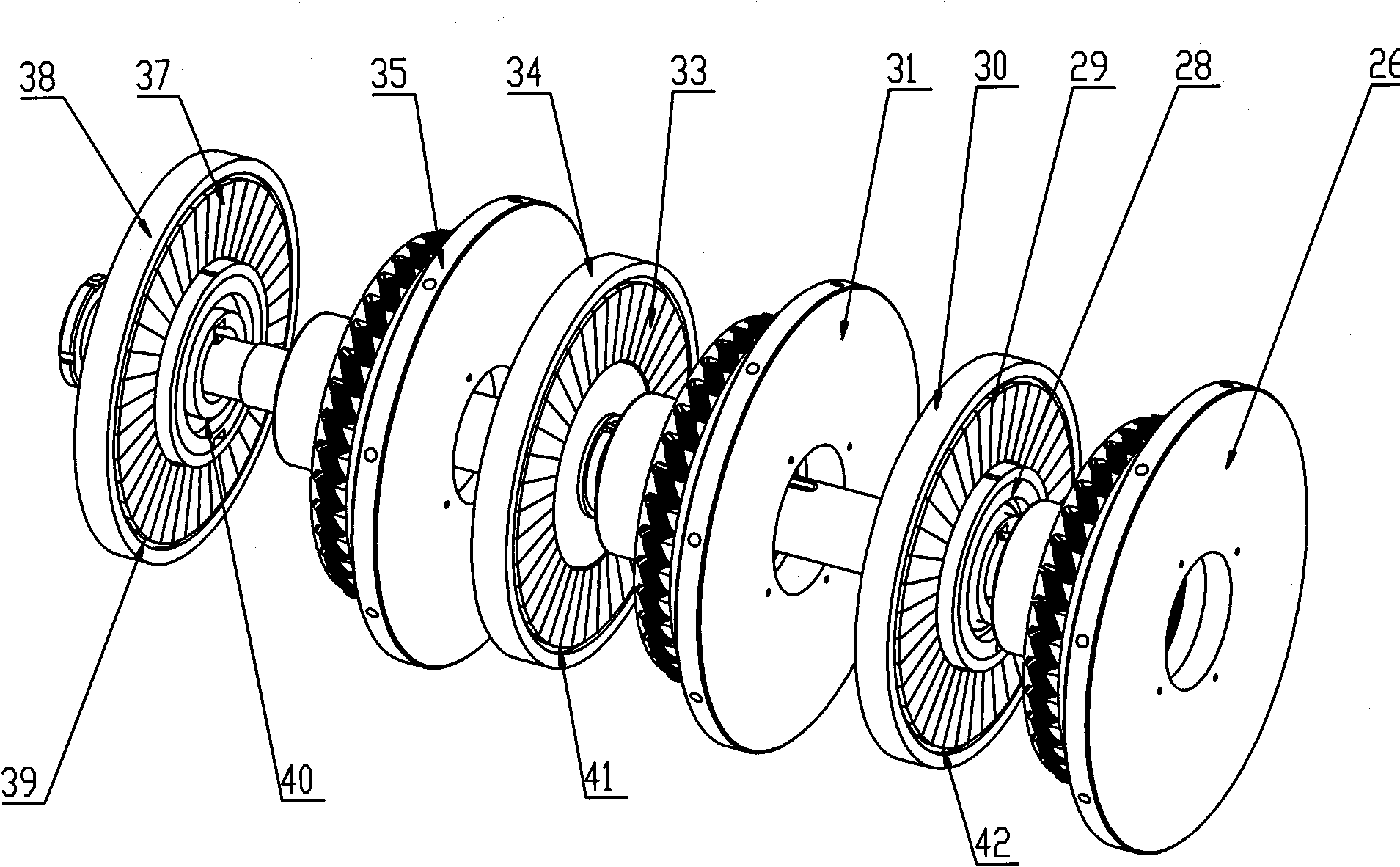
[0025] Such as figure 1 , 2 , 3, and 4, the disc permanent magnet synchronous multi-combination power DC motor unit 11 includes a casing, the casing is composed of a lower casing 3 and an upper casing 5, and the lower casing 3 and the upper casing 5 are provided with The fixing screw 4, the lower casing 3 is provided with a base 1, the casing 3, 5 is also provided with a synchronous multi-combination power motor stator fixing screw 6 and plays a fixing role, and an insulating material 14, 17 is also provided with an insulating effect, The junction box 9 is provided with a power cord, and the whole motor is fixed by the fixing screws 2 on the base 1 . The pole pairs of the three motors are 10-40 pairs, and uneven air gaps are used. Of course, the number of motors here can be increased or decreased according to needs, but there must be at le...


PUM


Abstract

The invention discloses a disc permanent-magnet synchronous multi-combination power DC motor group, which comprises a motor casing. A main power shaft is arranged in the motor casing, at least two groups of motors are arranged in the motor casing, rotors of one group of motors are fixedly connected with the main power shaft, and rotors of the rest groups of motors are connected with the main power shaft through a clutch. When the disc permanent-magnet synchronous multi-combination power DC motor group is used on an electric motorcar and the electric motorcar is started, all motor rotors of the DC motor group are all connected with the main power shaft, thereby driving the electric motorcar to be quickly started, shortening start speed-raising time of the electric motorcar, shortening discharge time of raising high-current speed, and reducing electric power consumption. When the electric motorcar reaches a certain speed, the electric motorcar can automatically shut off one group or two groups of motors, the rotors of the motors are disconnected with the main power shaft so that the power and the energy of the motors are exerted more reasonably, and each group of motors are ensured to work in the working state of the maximum efficiency point.

Description

technical field [0001] The invention relates to a DC motor, in particular to a disc-type permanent magnet synchronous multi-combination power DC motor unit. Background technique [0002] At present, the working principle of the traditional column motor has the following shortcomings that cannot be solved: [0003] 1) The traditional column-type DC high-power motor with a power of 10 kW or more is very large. If it is used on a city bus, it needs to use a power of 60-120 kW or more. First, its volume cannot be guaranteed on a bus. Large adjustments, and greatly increase the cost of the vehicle. According to the use of 60 kilowatts DC motor on the bus, if the voltage of 300 volts is used when starting, it needs a large current of 1000 amperes to start. If the starting current above 300 volts and 1000 amps cannot be guaranteed, the speed-up time of the vehicle will be prolonged, resulting in long-term high-current discharge of the battery, and the continuation mileage of the ...

Claims


Application Information

Patent Timeline
Patent Type & Authority Applications(China)
IPC IPC(8): H02K21/24H02K7/10H02K29/08H02K1/27
Inventor 沈坤元
Owner SUZHOU BOZUN SCI & TECH
Learn More