
Power supply control method and terminal equipment

A terminal equipment and power control technology, applied in the field of communication systems, can solve problems such as failure to optimize power consumption, waste of time for stable environment conversion, waste of power consumption, etc., so as to prolong standby and use time and reduce power consumption. , make up for the effect of running time

Inactive Publication Date: 2010-11-17
扬州易狄欧电子科技有限公司
View PDF3 Cites 2 Cited by
  • Summary
  • Abstract
  • Description
  • Claims
  • Application Information

AI Technical Summary

Problems solved by technology

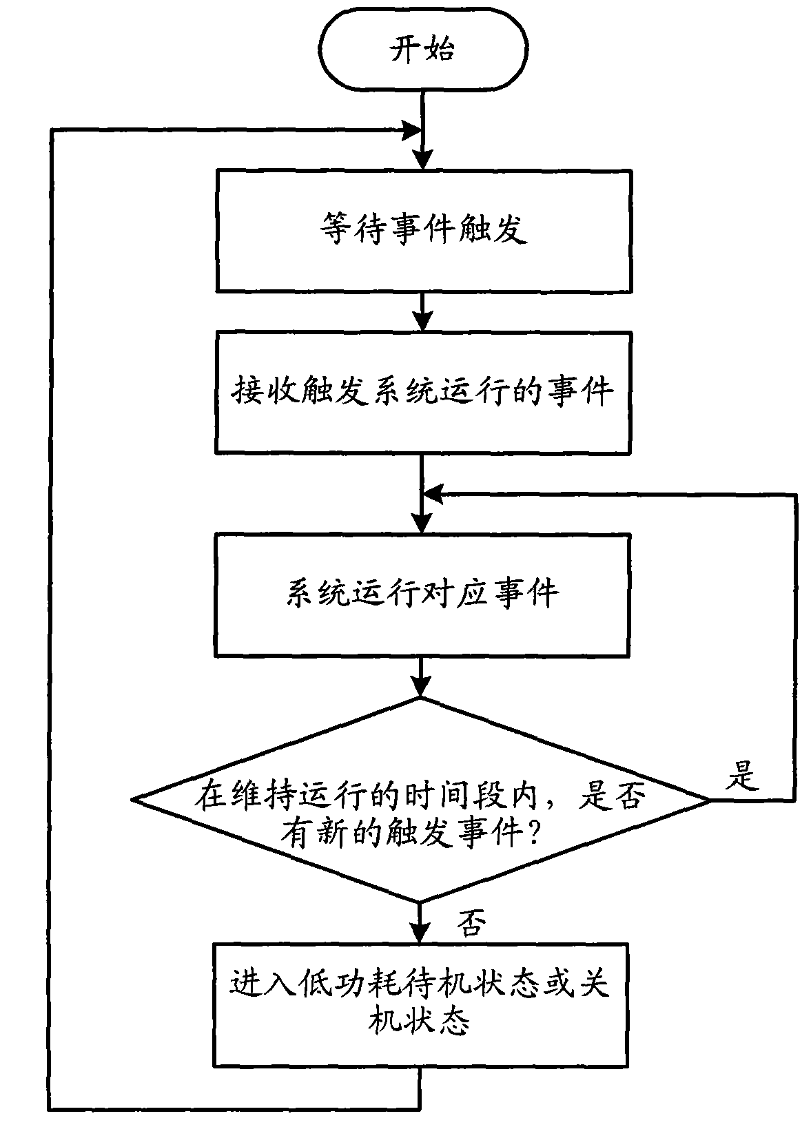
However, the operating environment required for different tasks such as operating voltage and operating frequency may be different. If the same operating environment is used uniformly, it will actually cause waste of power consumption.
Although some solutions change the operating environment according to the complexity of the event after the system is running, it also wastes the time required to stabilize the environment conversion, and does not optimize the reduction of power consumption.

Method used


Image

  • Power supply control method and terminal equipment
  • Power supply control method and terminal equipment
  • Power supply control method and terminal equipment

Examples


Embodiment Construction

[0024] In the following description, many technical details are proposed in order to enable readers to better understand the application. However, those skilled in the art can understand that without these technical details and various changes and modifications based on the following implementation modes, the technical solution claimed in each claim of the present application can be realized.

[0025] In order to make the purpose, technical solution and advantages of the present invention clearer, the following will further describe the implementation of the present invention in detail in conjunction with the accompanying drawings.

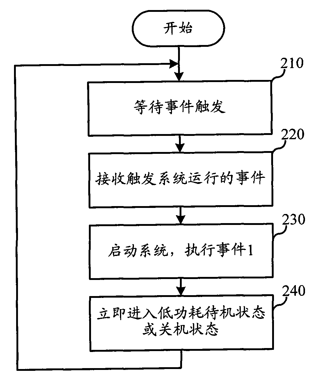
[0026] The first embodiment of the present invention relates to a power control method, the specific process is as follows figure 2 shown.

[0027] In step 210, the terminal device waits for an event trigger. Specifically, in general, in order to save power, the terminal device is in a low power consumption state when there is no task to run, a...


PUM


Abstract

The invention relates to a communication system and discloses a power supply control method and terminal equipment, which effectively reduces the power consumption of the terminal equipment and prolongs the standby and using time of the terminal equipment. In the invention, the terminal equipment immediately converts the state of a power supply into a low power consumption state after executing an external event for triggering a system to operate. Further, the terminal equipment can effectively make up the running time on restarting the system through modes of storing running parameters, maintaining clock signals and the like, thereby not only reducing the running time of the system but also further lowering the working consumption.

Description

technical field [0001] The invention relates to a communication system, in particular to a power supply control technology of terminal equipment in the communication system. Background technique [0002] With the full rollout of the global 3G network and the vigorous promotion of terminal equipment and related component technologies, users' application of wireless communication networks has reached an unprecedented height. In order to cater to the market demand, various manufacturers have launched terminal equipment (such as mobile phones, handheld game consoles, etc.) with various entertainment and communication functions. Taking the mobile phone as an example, its functions have gradually evolved from the initial monochrome display screen, simple call function and support for sending and receiving short messages to today's text reading, email, game download / multiplayer game, Internet browsing, music download, Satellite positioning and electronic wallets, etc., are quickly...

Claims


Application Information

Patent Timeline
Patent Type & Authority Applications(China)
IPC IPC(8): H04M1/73G06F1/32
CPCY02D30/70
Inventor 朱伟王骞李晶叶立飞薛新华
Owner 扬州易狄欧电子科技有限公司
Learn More