Motorcycle oil-gas separator

A technology of oil and gas separators and motorcycles, which is applied in the direction of machine/engine, engine components, engine lubrication, etc., can solve the problems of air pollution, violation, and limited adsorption capacity of carbon tanks, so as to avoid entering carbon tanks and make the manufacturing process simple , The effect of convenient installation

Inactive Publication Date: 2010-09-22
CHONGQING LONCIN MOTOR
View PDF6 Cites 3 Cited by
  • Summary
  • Abstract
  • Description
  • Claims
  • Application Information

AI Technical Summary

Problems solved by technology

[0003] Although the entrance of the fuel evaporator pipe is generally higher than the fuel level when the motorcycle is in use, the fuel will not enter the pipeline under normal circumstances, but due to the complexity of the motorcycle driving situation, violent bumps may occur from time to time, especially when the oil level When it becomes higher and higher than the inlet of the fuel evaporation pipe, the fuel in the fuel tank may also enter the carbon canister through the fuel evaporation pipe, and the adsorption capacity of the carbon canister itself is very limited, so the fuel will flow out of the carbon canister and pollute the atmosphere; this is Violated the national III fuel evaporation control requirements
[0004]In order to prevent this from happening, some existing technologies shrink the inlet of the fuel evaporator pipe or add stoppers, but it still cannot completely prevent the fuel tank from The fuel enters the carbon tank through the fuel evaporation tube
The existing oil and gas separator cannot be installed in the fuel tank, and the structure is complicated

Method used


Image

  • Motorcycle oil-gas separator
  • Motorcycle oil-gas separator
  • Motorcycle oil-gas separator

Examples


Embodiment Construction

[0015] The present invention will be further described below in conjunction with accompanying drawing.

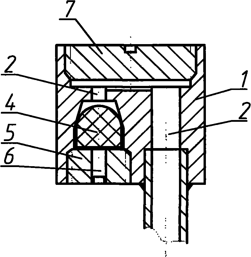
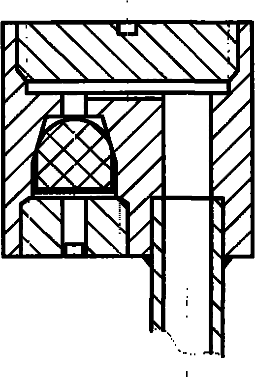
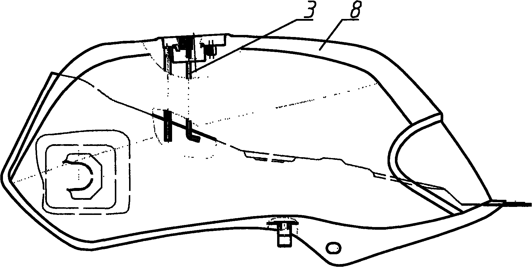
[0016] see figure 1 , as can be seen from the figure, the motorcycle oil-gas separator of the present invention includes a separator body 1, and an oil vapor passage 2 is arranged in the separator body 1, the inlet of the oil vapor passage 2 is a bell mouth, and the outlet of the oil vapor passage 2 Connect with the carbon canister through the oil vapor vent pipe 3. A float 4 is arranged in the bell mouth, and the float is a non-metallic part whose density is lower than that of fuel oil. The limiter 5 is threadedly connected to the bell mouth of the separator body 1, and usually the float falls on the limiter. A through hole 6 is provided at the center of the limiting member 5, and a ventilation groove is provided on the bottom surface of the float, and the ventilation groove communicates with the through hole. Once fuel oil enters the through hole of the limiting member...


PUM


Abstract

The invention discloses a motorcycle oil-gas separator. An oil vapor channel is arranged in the separator body; an inlet of the oil vapor channel is a bell mouth; the outlet of the oil vapor channel is connected with a carbon tank through an oil vapor vent pipe; a floater is arranged in the bell mouth; the position at the bell mouth and on the separator body is in threaded connection with a stopper, and the floater can float up and down between the bell mouth and the stopper; a through hole is arranged on the stopper; and the bottom of the floater is provided with a vent groove communicated with a through-hole The oil-gas separator of the invention is fixed on the top of an oil tank, oil vapor can smoothly passes the separator to enter into the carbon tank, the floater floats upwards immediately to block the channel once fuel enters into the separator, thus the fuel cannot pass through the channel. The oil-gas separator has simple manufacturing process and convenient and reliable fixed installation, can effectively separate oil and gas, and avoid the entering of the fuel to the carbon tank.

Description

technical field [0001] The invention relates to an oil-gas separator used on a motorcycle. The oil-gas separator is installed in the fuel tank and is located at the highest point of the fuel tank. Vehicle State III fuel evaporation control requirements. Background technique [0002] With the continuous improvement of environmental protection standards, the requirements for motorcycles are becoming more and more stringent. In addition to strict control of exhaust emissions, it is also required to control and treat the oil vapor generated in the fuel tank, that is, the oil vapor cannot be directly discharged into the atmosphere. After some treatment. In order to meet the requirements of environmental protection on emissions (such as Euro III standards), the existing technology directly introduces the oil vapor in the motorcycle fuel tank into the carbon tank through the pipeline, which is first adsorbed by the carbon tank and then desorbed into the engine to participate in co...

Claims


Application Information

Patent Timeline
Patent Type & Authority Applications(China)
IPC IPC(8): F01M11/08
Inventor 苟孝贵彭志强江海
Owner CHONGQING LONCIN MOTOR
Why Eureka
Try Eureka