Light condensing solar conversion system

A solar energy conversion and concentrating technology, applied in the field of solar energy conversion systems, can solve the problems of loss of light information and energy, different refraction angles, unfavorable light propagation, etc., and achieve the effects of improving solar energy conversion efficiency, high utilization rate and reasonable design.

Inactive Publication Date: 2013-06-26
江苏尚恩合同能源管理有限公司
View PDF4 Cites 2 Cited by
  • Summary
  • Abstract
  • Description
  • Claims
  • Application Information

AI Technical Summary

Problems solved by technology

Especially for the focused beam, each light in the beam has different incident angles on the incident surface. When the beam enters the light guide column, complex refraction will occur on the incident surface, which is not conducive to the propagation of light in the light guide column.
In severe cases, even some light in the beam will be totally reflected on the incident surface and cannot enter the light guide column, thus losing the information and energy carried by this part of the light
[0008] Moreover, when the light guide column is used to transmit white light (especially sunlight), since white light (sunlight) is composed of multiple monochromatic lights, even if the incident angles of various monochromatic lights on the incident surface are the same, the refraction angle will generally be different. Different, it will cause dispersion; in severe cases, even some monochromatic light will form total reflection on the incident surface, unable to enter the light guide column, thus losing the information and energy carried by the monochromatic light

Method used


Image

  • Light condensing solar conversion system
  • Light condensing solar conversion system

Examples


Embodiment Construction

[0043] The specific implementation manners of the present invention will be further described below in conjunction with the drawings and examples. The following examples are only used to illustrate the technical solution of the present invention more clearly, but not to limit the protection scope of the present invention.

[0044] The technical scheme of concrete implementation of the present invention is:

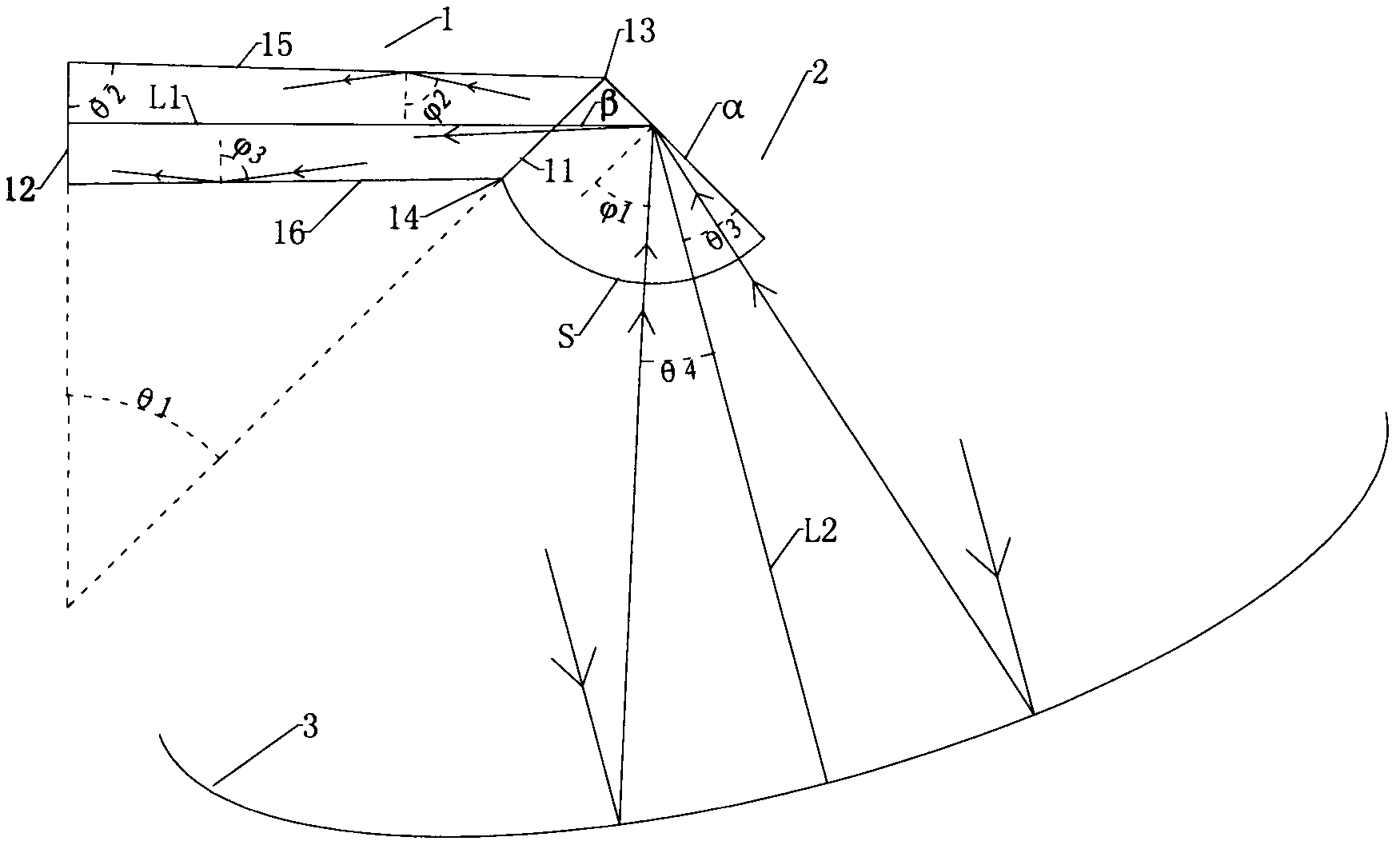
[0045] A concentrating solar energy conversion system, comprising a parabolic mirror 3, a light guiding column and a light receiving device 4;

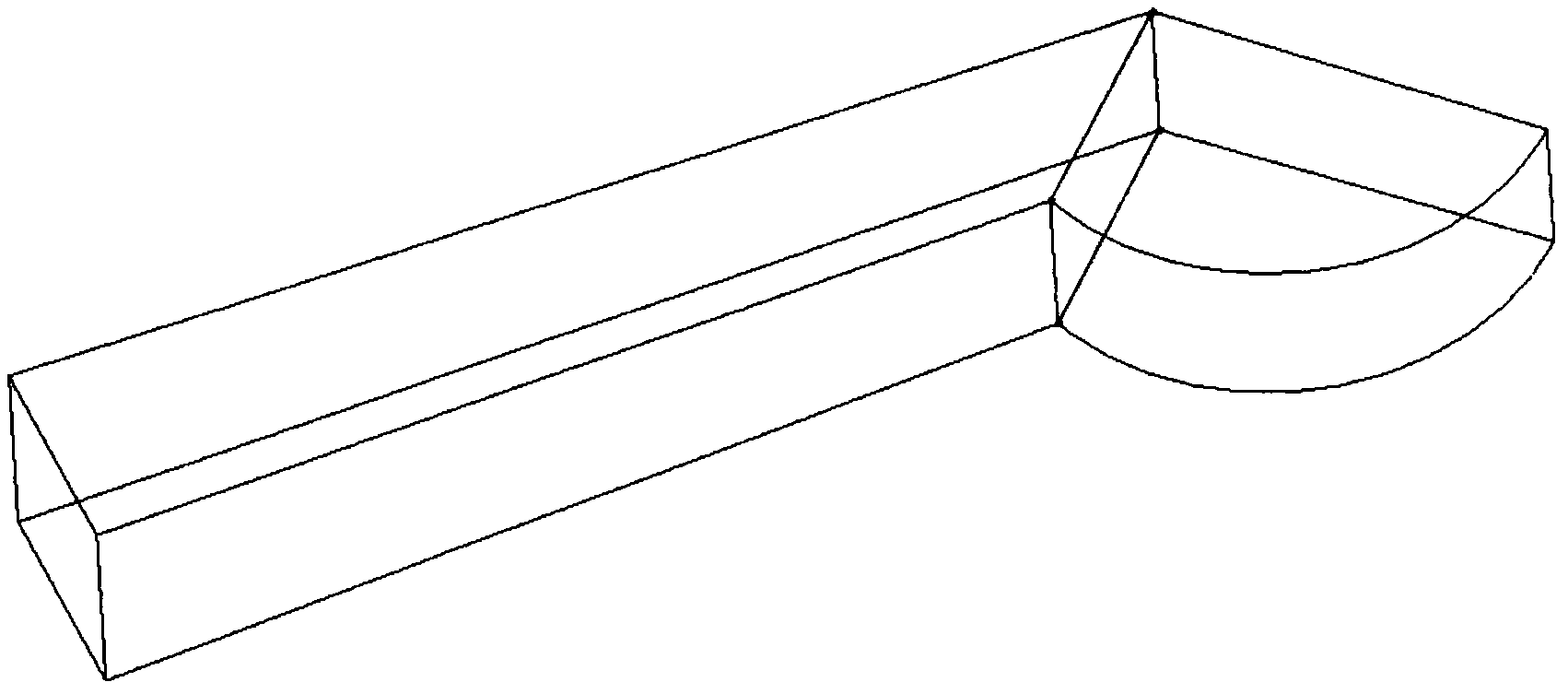
[0046] The light guide column includes a first light guide block 1 and a second light guide block 2 with the same refractive index;

[0047] The first light guide block 1, its geometric shape is the part between the section 11 and the bottom surface 12 left after a regular quadrangular pyramid is truncated by the first plane, and the bottom surface 12 is the regular quadrangular pyramid bottom surface 12; the first plane and the ...


PUM


Abstract

The invention discloses a light condensing solar conversion system which comprises a paraboloid mirror, a light guide column and a light receiving device. The light guide column is provided with a first light guide block and a second light guide block which are the same in refractive index. The geometrical shape of the first light guide block is a part reserved between a section and a bottom when a right square pyramid is sectioned by a first plane. The first light guide block and the second light block uses the section as a combining face. The light receiving device comprises a photovoltaic conversion device and a photothermal conversion device. By the light condensing solar switching system, parallel sunlight beams can be focused, complex refraction of focused light on a incident plane of the light guide column is avoided or reduced, the focused light can totally enter the light guide column, loss of some light in the focused light due to the fact that some light is totally reflected at a light input end of the light guide column is prevented, information and energy carried by the focused light can be guaranteed to enter the light guide column, be transmitted in the light guide column effectively, and finally be transmitted to the light receiving device, solar energy can be converted into electric energy and thermal energy, and high solar energy utilization rate is achieved.

Description

technical field [0001] The invention relates to a solar energy conversion system, in particular to a concentrating solar energy conversion system comprising a parabolic mirror, a light guide column and a light receiving device. Background technique [0002] Solar energy is an ideal energy source and is widely used. Due to the volume ratio of the sun to the earth and the distance between the sun and the earth, the sunlight used by people can be regarded as a parallel beam. If this parallel beam is directly used for solar energy conversion, The effect is mediocre, and it is better to gather parallel solar beams, which will improve the solar energy conversion efficiency. [0003] Parabolic mirrors can be used to focus parallel light beams (sunlight). When the incident parallel light beams are parallel to the main axis of the parabolic mirror, the parallel light beams will be focused at the focal point of the parabolic mirror. Therefore, parabolic mirrors are widely used. [0...

Claims


Application Information

Patent Timeline
Patent Type & Authority Applications(China)
IPC IPC(8): H01L31/052F24J2/12F24J2/46G02B19/00G02B6/00F24S23/71H02S40/22
CPCY02E10/40Y02E10/52
Inventor 叶剑锋叶萌竹
Owner 江苏尚恩合同能源管理有限公司
Why Eureka
Try Eureka