Eureka AIR delivers breakthrough ideas for toughest innovation challenges, trusted by R&D personnel around the world.

Hydrogen generating apparatus using steam reforming reaction

A technology of steam reforming and hydrogen, applied in hydrogen/synthesis gas production, hydrogen, inorganic chemistry, etc., can solve the problems of weakening stability and durability, thermal deformation of supporting parts, etc., to improve overall durability and stability, Effect of preventing deformation and damage

Active Publication Date: 2010-09-22
SK INNOVATION CO LTD
View PDF0 Cites 4 Cited by
  • Summary
  • Abstract
  • Description
  • Claims
  • Application Information

AI Technical Summary

Problems solved by technology

[0020] However, the reformer according to the prior art has a problem that since the catalyst tube is heated to a high temperature by the heat of reaction, the supporting member supporting the catalyst tube will be thermally deformed, thereby greatly impairing stability and durability.

Method used


Image

  • Hydrogen generating apparatus using steam reforming reaction
  • Hydrogen generating apparatus using steam reforming reaction
  • Hydrogen generating apparatus using steam reforming reaction

Examples


Embodiment Construction

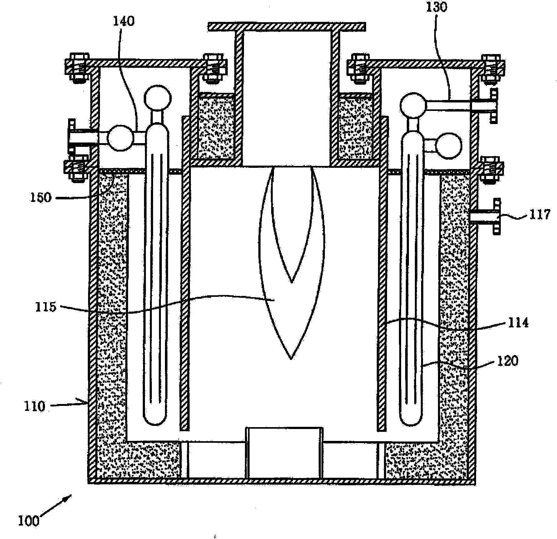
[0041] Hereinafter, preferred embodiments of an apparatus for generating hydrogen using steam reforming according to the present invention will be described in detail with reference to the accompanying drawings.

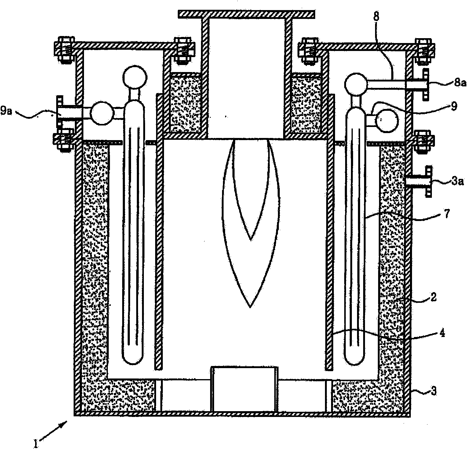
[0042] image 3 is a sectional view showing the configuration of an apparatus for generating hydrogen using steam reforming according to the present invention.

[0043] Such as image 3 As shown, the device 1 for generating hydrogen by steam reforming of the present invention roughly includes: a housing 3; a flame guide 4, which limits a combustion portion 5 disposed in the housing 3; a plurality of catalyst tubes 7, which are vertically disposed on In the space separated from the combustion part in the casing 3; the raw material supply manifold 8, which supplies the raw material to each catalyst tube 7; and the reformed product manifold 9, which discharges the reformed product obtained in each catalyst tube 7 to outside; and a support member 10 for supporting each...


PUM


Abstract

Disclosed herein is an apparatus for generating hydrogen by steam reforming. The apparatus comprises: a casing having provided in the central portion thereof a combustion section for producing high-temperature reaction heat; a flame guide provided such that it forms the outer wall of the combustion section while a space is provided outside thereof; a plurality of catalytic tubes arranged concentrically with respect to the combustion section in the space outside the flame guide; a feed supply manifold disposed at one side of the inside of the casing so as to distribute a feed supplied from the outside of the apparatus to each of the catalytic tubes; a reformate manifold connected with one end of each of the catalytic tubes so as to discharge a reformate obtained by the reforming reaction to the outside of the apparatus; and a support member which consists of an inner ring plate formed at one side of the inside of the casing and an outer ring plate disposed concentrically around the outer circumference of the inner ring plate and which has formed at the boundary between the inner and outer ring plates tube holes into which one end of each of the catalytic tubes is inserted. In the hydrogen generating apparatus, the structure of the support member supporting the plurality of catalytic tubes is simply divided into the inner ring plate and the outer ring plate, such that the expansion and shrinkage of the support member by thermal stress can be efficiently compensated for. As a result, deformation and breakdown of the support member caused by thermal stress can be prevented, thus improving the overall durability and stability of the hydrogen generating apparatus.

Description

technical field [0001] The present invention relates to a device for generating hydrogen by steam reforming, which continuously supplies hydrogen through a steam reforming reaction of natural gas or hydrocarbons. More particularly, the present invention relates to an apparatus for generating hydrogen using steam reforming, in which a support member for supporting a catalyst tube where a high-temperature reforming reaction occurs has an improved structure and increased durability, thereby ensuring stable performance and reliability. Background technique [0002] In recent years, due to the gradual increase in energy consumption with the development of technological innovation, the shortage of fossil fuel reserves and environmental pollution problems need to be solved urgently. At the same time, people's interest in hydrogen energy using clean hydrogen fuel as an energy carrier is also increasing. However, in the process of producing hydrogen from alternative energy sources (...

Claims


Application Information

Patent Timeline
Patent Type & Authority Applications(China)
IPC IPC(8): C01B3/38
CPCC01B2203/1064B01J8/025C01B2203/0816B01J8/062B01J2208/00504C01B3/384B01J8/0257C01B2203/1058C01B2203/0233B01J2208/00495C01B3/26C01B3/38
Inventor 崔宰硕金明俊金荣大
Owner SK INNOVATION CO LTD
Why Eureka
Eureka Blog
Learn More