

Welding carriage
A welding trolley and automatic welding technology, which can be applied to the field of horizontal parts and vertical parts, can solve the problems of difficulty in tracking the welding line and easy separation from the welding line, and achieve the effect of preventing safety accidents and stabilizing welding operations.
Inactive Publication Date: 2010-09-29
CHUNGSONG IND
View PDF7 Cites 5 Cited by
- Summary
- Abstract
- Description
- Claims
- Application Information
AI Technical Summary
Problems solved by technology
Therefore, various methods have been proposed for tracking the welding line, but it is difficult to track the correct welding line when welding in a shape, and it is very easy to get out of the welding line during the movement of the welding carriage.
Method used
View moreImage
Smart ImageViewing Examples


Examples
Embodiment Construction
Login to View More PUM
 Abstract
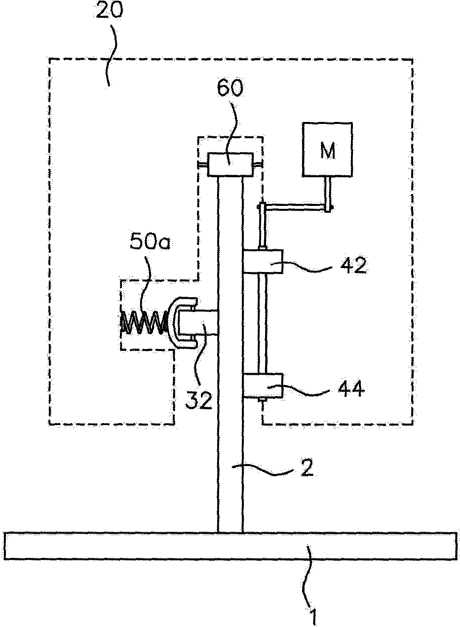
The invention relates to a welding carriage, comprising a main body which includes a horizontal member and a vertical member; a pincer clamp portion arranged on two sides of the main body for setting a pair of welding torches; a drive portion arranged on the lower side of the main body for moving the main body; wherein the drive portion includes a drive motor; a drive wheel member connected to the drive motor and moving along a lateral surface of the vertical member; a guide wheel member includes guide wheels on the other lateral surface of the vertical member; the drive wheel member moves in a way of abutting against the upper surface of the vertical member when the main body moves and it includes a pair of upper wheels which are arranged along the vertical direction and a pair of lower wheels which are disposed at a position having a certain distance from the upper wheels and the diameter of the lower wheels is smaller than that of the upper wheels. The drive wheel is characterized in that when the main body moves, the drive wheel is able to abut against the vertical member to move, so that the upper wheel diameter of the drive wheel moving along the upper surface of the vertical member is greater than that of the lower wheel, thus guaranteeing the main body to move along the upper surface of the vertical member and automatically welding the shape connection part of the horizontal member and the vertical member.
Description
technical field The invention relates to a welding trolley, especially a welding trolley that can be used for horizontal parts and vertical parts Background technique Assembling equipment by welding is still one of the main work methods in the entire industrial field, and there are many differences in welding quality, etc., depending on the proficiency of the operator. Moreover, because a lot of harmful gas is produced during the welding process, which is not conducive to the health of welding operators, so welding methods should not be used as much as possible. Therefore, an automatic welding trolley that can improve work efficiency and save high labor costs has been developed to perform automatic welding on specific parts. Especially in steel structures such as propagation, when welding vertical parts on horizontal parts, such as Korean Patent Office Patent Application No. 20-2002-0000983, etc., it is recommended to use such a welding trolley. For such a welding trol...
Claims
Login to View More Application Information
Patent Timeline
 Patent Type & AuthorityApplications(China)
IPC IPC(8): B23K37/02
CPCB23K9/12B23K9/327B23K37/0247B23K37/0282B23K37/0294
Inventor玉光浩
OwnerCHUNGSONG IND