
Sister connector

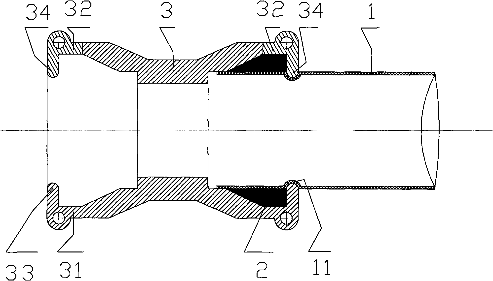
A connecting piece and ring piece technology, applied in the direction of sleeve/socket connection, pipe/pipe joint/pipe fitting, passing element, etc., can solve the problems of poor reliability, inapplicability, poor sealing stability, etc., and achieves installation convenience and precision. Less convenience, guaranteed stability and sealing effect

Inactive Publication Date: 2010-09-29
舒金发
View PDF1 Cites 3 Cited by
  • Summary
  • Abstract
  • Description
  • Claims
  • Application Information

AI Technical Summary

Problems solved by technology

In the practical application of the pipe fitting joint with this structure, there are the following problems: 1. The sealing is achieved by using the external connection wire, that is, the port slope of the connector and the sealing ring. Under the influence of vibration and shaking factors, the sealing stability is poor
2. After the bushing is added in the pipe body, although the misalignment problem between the connecting piece and the pipe is solved, it is beneficial to avoid the influence of vibration, shaking and other factors on the seal, but the structure becomes complicated, and the double bushing and sealing It is difficult to coordinate the fixed and sealing ratio of the ring, and it will also affect the smooth flow of conveyed materials, especially not suitable for small-diameter pipe connections
For large-diameter pipes, there are difficulties in the double-layer structure between the pipe body and the bushing, and precipitation corrosion and sediment rot are prone to occur in the gap between the bushings, which will affect the service life of the connectors and the pipe body, and the reliability is poor.

Method used


Image

  • Sister connector
  • Sister connector
  • Sister connector

Examples


Embodiment Construction

[0015] see figure 1 , and combined with figure 2 and image 3 , figure 1 It is a structural cross-sectional view of this embodiment after the assembly is completed;

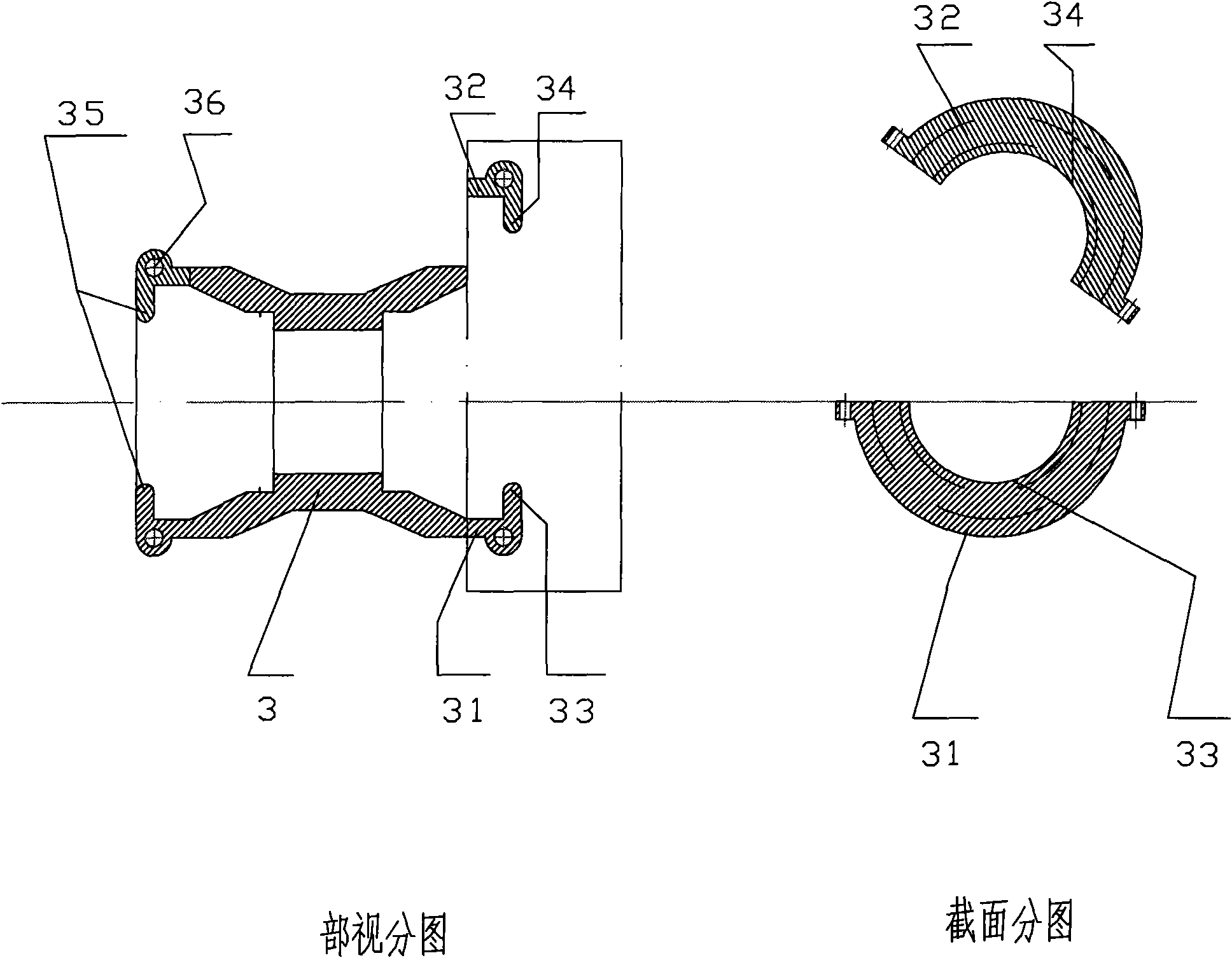
[0016] figure 2 It is a detailed illustration of the connection end of this embodiment. The cross-sectional view in the figure shows the schematic diagram of the connection port in the connected state and the separated state (in the frame), and the cross-sectional view in the figure shows the connector on the cross-sectional view. A cross-sectional schematic diagram of the separated end (that is, the part in the frame);

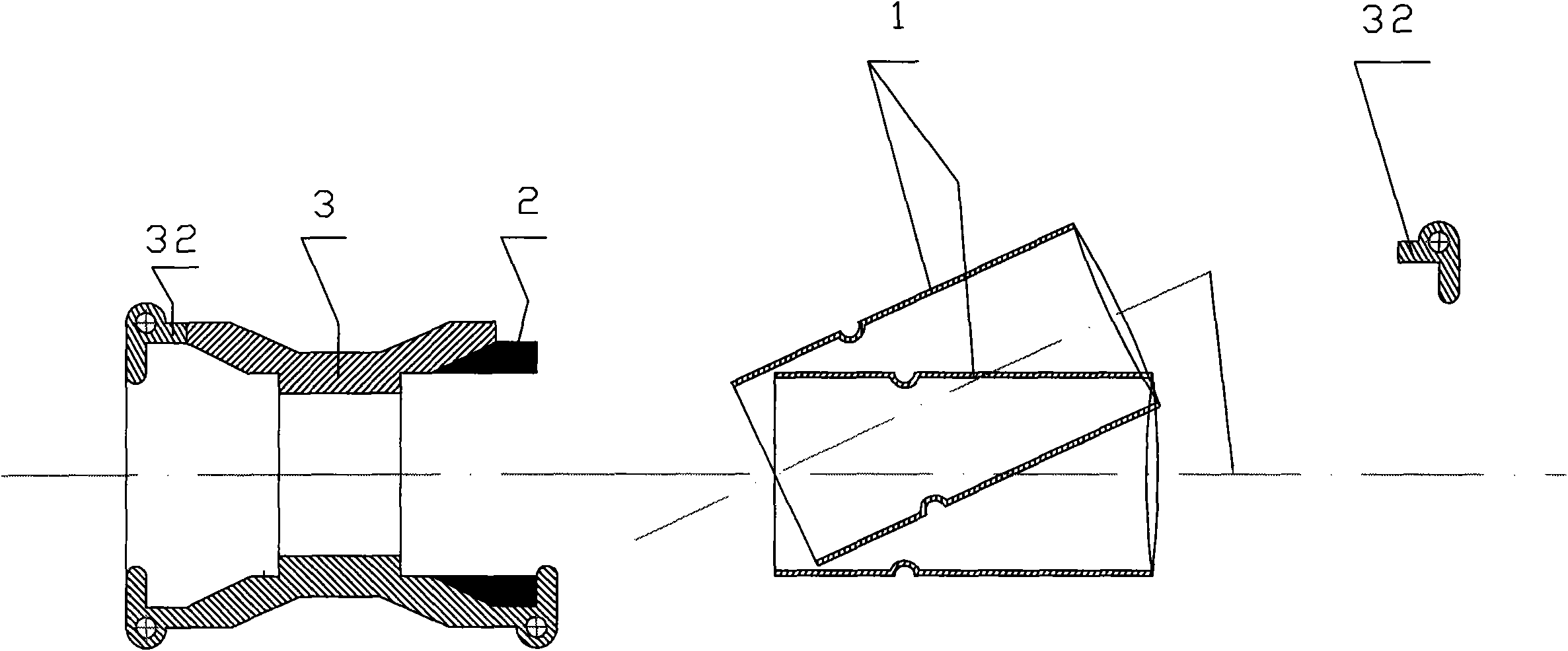
[0017] image 3 It is a cross-sectional view of each component of this embodiment when assembled;

[0018] Figure 4 It is a structural cross-sectional view of another design of the pipe body after assembly in this embodiment;

[0019] Look image 3 , recombine figure 2 , according to the assembly sequence, from left to right, there are connection 3, sealing ring 2, pipe body 1 and ...


PUM


Abstract

A sister connector comprises a pipe body, a seal ring, a connecting piece and a loop piece. The pipe body is in sister connection on the loop end of the connecting piece through the loop piece and is fixed on the connecting piece, the pipe body is provided with a concave loop, the loop end of the connecting piece and the loop piece can form an integrated loop shaped port, and the connecting piece and the loop piece are both provided with convex strips which can form a convex loop through the sister connection. When the connector is installed, the pipe body with the concave loop is aslant inserted into the seal ring arranged in the cavity of the connecting piece, and the pipe body is aligned on the same central axis of the connecting piece, and the convex strip on the loop end of the connecting piece is stuck in the concave loop of the pipe body just right, the loop piece is in sister connection on the loop end of the connecting piece, and the convex strip thereof is stuck in the concave loop of the pipe body simultaneously and is in sister connection with the convex strip on the loop end of the connecting piece to form the convex loop, thereby locking the pipe body tightly to achieve the connection. The connection of the invention has the characteristics of compact structure, less and reasonable components, safe and convenient production, simple process and good practicability.

Description

【Technical field】 [0001] The Hehe connector belongs to a connector for transporting liquid, gas, etc., and is especially suitable for the connection of thin-walled pipelines with sealing requirements. 【Background technique】 [0002] In the structure where pipes and pipes are connected to each other through connectors, one of the biggest problems is how to ensure that the connection between the connector port and the pipe port is firm and sealed, especially when the structure is affected by factors such as vibration and shaking. The cost of materials can be reduced, and the effect of stability and sealing can be well achieved. [0003] ZL02242868.2 discloses a "pipe joint". Its structure includes a pipe body, nuts and external wires. There is a groove on the pipe wall at the front of the pipe body, a snap ring is arranged in the groove, and a sealing ring is arranged in front of the snap ring to increase the strength of the thin-walled pipe. , a bushing is provided in the i...

Claims


Application Information

Patent Timeline
Patent Type & Authority Applications(China)
IPC IPC(8): F16L21/06
Inventor 舒金发
Owner 舒金发
Learn More