Check patentability & draft patents in minutes with Patsnap Eureka AI!

Backlight module

A backlight module, light guide plate technology, applied in optics, light guides, light sources, etc., can solve problems such as affecting the competitiveness of the display, uneven light intensity, and lowering the quality of the display

Inactive Publication Date: 2013-01-16
华映视讯(吴江)有限公司 +1
View PDF0 Cites 0 Cited by
  • Summary
  • Abstract
  • Description
  • Claims
  • Application Information

AI Technical Summary

Problems solved by technology

[0004] However, please refer to Figure 1B , which is an enlarged view of a known side-lit backlight module. The path of the divergent light from the LED 120 is shown in the figure. The divergence angle of the LED 120 is 120 degrees, which is not a flat light of 180 degrees. Therefore, within the adjacent intervals of the LEDs 120 must There is a phenomenon of uneven light quantity, the light emitted by LED 1201 is the angle range from optical path 0 to optical path P, the light emitted by LED 1202 is the angular range from optical path Q to optical path R, and the angle between optical path P and optical path Q is During this period, there will be an area a that cannot be covered by the light, that is, the part that causes the hot spot (hot spot) and the dark block at the corner. Therefore, there is a hot spot between every two LEDs 120, resulting in uneven brightness
[0005] In view of the uneven brightness produced by the backlight module of the above-mentioned known technology, the quality of the display is reduced and the competitiveness of the display is affected. Therefore, relevant practitioners hope to propose a practical and effective solution to solve the aforementioned problems.

Method used


Image

  • Backlight module
  • Backlight module
  • Backlight module

Examples


Embodiment Construction

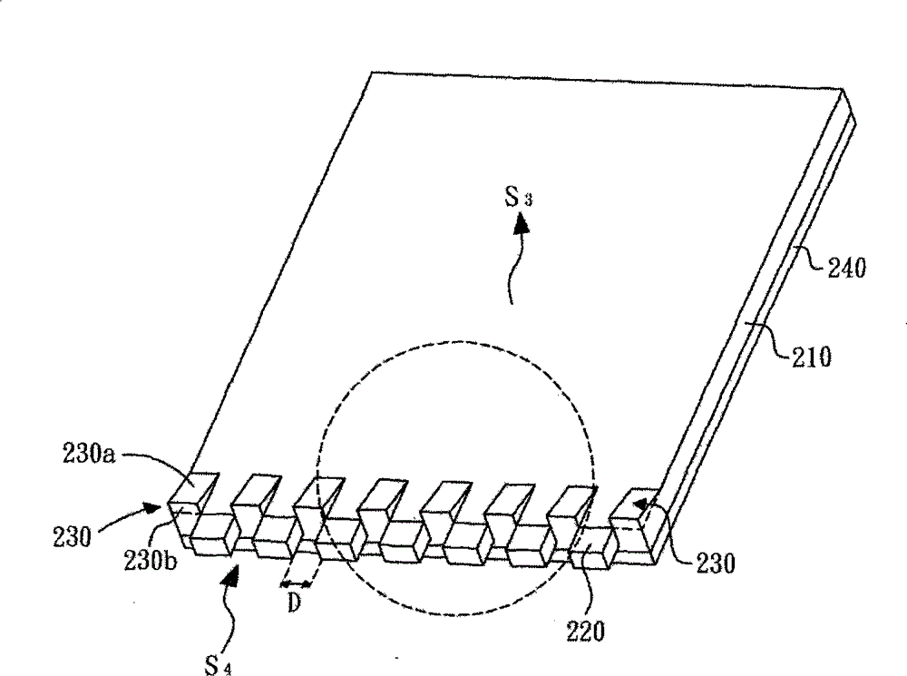
[0020] Please refer to Figure 2A , which is a schematic diagram of the first embodiment of the backlight module provided by the present invention. The backlight module of the present invention includes a light guide plate 210 , a plurality of LEDs 220 and a plurality of bumps 230 .

[0021] The light guide plate 210 has a light-emitting surface S3, a light-incident surface S4 connected to the light-emitting surface S3, and a bottom surface (not shown) opposite to the light-emitting surface S3, wherein the light-incident surface S4 is exactly located at one side of the light-emitting surface S3. side. As for, a plurality of LEDs 220 are distributed on the light incident surface S4 of the light guide plate 210 , and two adjacent LEDs 220 are separated by a distance D from each other. The plurality of protrusions 230 are disposed on the light-emitting surface S3 of the light guide plate 210 and arranged alternately with the LEDs 220 . That is to say, for each LED 220 , it is ...


PUM


Abstract

The invention discloses a backlight module, which comprises primary members of a light guide plate, a plurality of LEDs and a plurality of bumps, wherein the light guide plate is provided with a light emerging surface and a light incident surface connected with the light emerging surface. The plurality of LEDs are distributed on the light incident surface of the light guide plate, and the two adjacent LEDs are partitioned by a spacing. The plurality of bumps are arranged on the light emerging surface of the light guide plate and in staggered arrangement with the LEDs.

Description

technical field [0001] The invention relates to a backlight module, in particular to a design of a light guide plate of the backlight module. Background technique [0002] With the advancement of science and technology, various video products such as mobile phones, notebook computers, digital cameras, PDAs, LCD screens and other products are becoming more and more popular, which greatly increases the demand for LCD monitors. However, the LCD panel itself does not emit light. There is a backlight setting to be able to display, and the backlight module is mainly used as the backlight of the liquid crystal display. Generally, there are two types of backlight modules, including direct-type and side-light backlight modules. Among them, the side-light backlight module The main components of the group include circuit boards, light sources, reflectors, light guide plates, and diffuser plates. [0003] Please refer to Figure 1A , is a schematic diagram of a known technology edge-li...

Claims


Application Information

Patent Timeline
Patent Type & Authority Patents(China)
IPC IPC(8): G02F1/13357F21S8/00F21V8/00F21V7/04F21Y101/02
Inventor 叶格铭谢襦毅
Owner 华映视讯(吴江)有限公司
Features
  • R&D
  • Intellectual Property
  • Life Sciences
  • Materials
  • Tech Scout
  • Unparalleled Data Quality
  • Higher Quality Content
  • 60% Fewer Hallucinations
Learn More