Tubular column type instrument board framework visual detection positioning device of automobile
What is Al technical title?
Al technical title is built by PatSnap Al team. It summarizes the technical point description of the patent document.
A technology for visual detection and positioning devices, which is applied in the direction of measuring devices, optical devices, instruments, etc., can solve the problems that no one has proposed automatic positioning equipment, etc., and achieve the effect of simple structure, easy operation, and improved detection efficiency
Inactive Publication Date: 2011-07-06
JILIN UNIV
View PDF0 Cites 0 Cited by
Summary
Abstract
Description
Claims
Application Information
AI Technical Summary
This helps you quickly interpret patents by identifying the three key elements:
Problems solved by technology
Method used
Benefits of technology
Problems solved by technology
[0004] For the detection of the body panel skeleton, there is no literature report using computer vision technology for non-contact detection, and no one has proposed related automatic positioning equipment for detection
Method used
Image
Click on the blue label to locate the original text in one second.
Reading with bidirectional positioning of images and text.
Examples
Embodiment Construction
[0026] The present invention is described in detail below in conjunction with accompanying drawing:
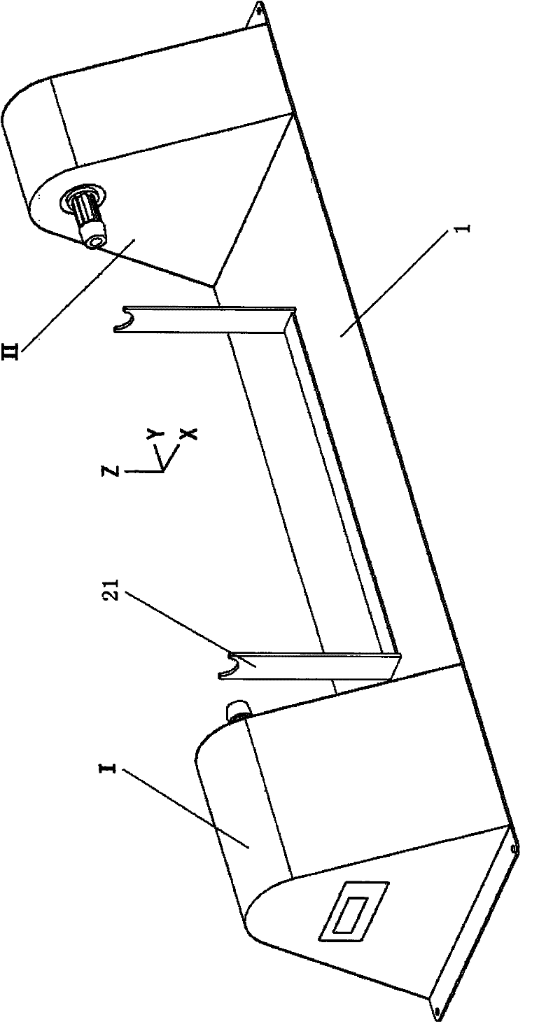
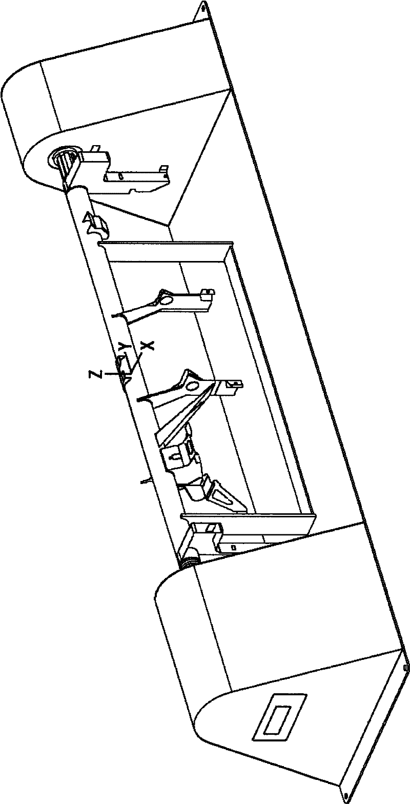
[0027] refer to figure 2 According to the present invention, the visual detection and positioning device for the framework of an automobile column instrument panel is composed of a base plate 1, a U-shaped support seat 21, a driving part I and a driven part II. The U-shaped supporting base 21 is fixed in the middle of the base plate 1 along the direction of the Y axis, and the driving part I and the driven part II are respectively fixed on the base plate 1 on the left and right sides of the U-shaped supporting base 21 .
[0028] The base plate 1 is a structural member of the plate type, and is made of a casting method or a steel plate. In the embodiment of the present invention, a flat steel plate with a thickness of 5mm is used. The base plate 1 is fixed on the foundation with evenly distributed bolts around it.
[0029] The U-shaped support seat 21 is a U-shaped structura...
PUM
Abstract
The invention discloses a tubular column type instrument board framework visual detection positioning device of an automobile. The positioning device comprises a base plate, a U-type supporting seat, a driving part and a driven part, wherein the driving part comprises a stepping driver I, a stepping driver II, a programmable motion controller, a rack guide-rail groove, a rack, a gear, a shift fork, a base I, a base II, a cone wheel I, a spline shaft A, a splined hub A, a V-type belt, a stepping motor I, a belt pulley and a stepping motor II; the driven part comprises a cone wheel II, a splineshaft B, a splined hub B, a base III, a base IV, a spring seat and a spring seat cover; the U-type supporting seat is formed by welding a left ground jack, a right ground jack and a bottom cross beam; the upper ends of the left ground jack and the right ground jack are processed into uniform semi-circle notches; the U-type supporting seat is fixed at the middle of the base plate, and the driving part and the driven part are fixed at the base plate on the two sides of the U-type supporting seat; and the line of the centers of the two semi-circle notches in the U-type supporting seat is collinear with the axial symmetric line of the castellated spline A and the spline shaft B.
Description
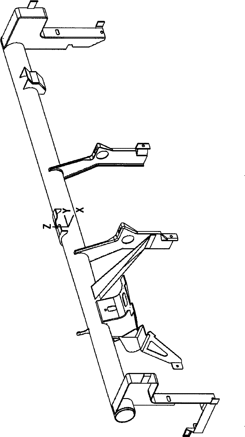
technical field [0001] The invention relates to a workpiece automatic fixing device in the field of computer vision detection, more specifically, the invention relates to a visual detection and positioning device applied to the skeleton of an automobile column instrument panel. Background technique [0002] The body is the largest assembly of a car, and its quality has a great influence on the overall function of the car. The complexity of the industrial site makes it inevitable that some errors will occur in the manufacturing process. In order to improve product quality, the quality control of the manufacturing process must be carried out, and the key to control is measurement. Therefore, the testing equipment and methods determine the accuracy and effectiveness of the body parts manufacturing and assembly process. [0003] refer to figure 1 , the figure shows the axonometric projection view of the two sides of the BORA car dashboard skeleton. At present, the car dashboar...
Claims
Application Information
Patent Timeline
Application Date:The date an application was filed.
Publication Date:The date a patent or application was officially published.
First Publication Date:The earliest publication date of a patent with the same application number.
Issue Date:Publication date of the patent grant document.
PCT Entry Date:The Entry date of PCT National Phase.
Estimated Expiry Date:The statutory expiry date of a patent right according to the Patent Law, and it is the longest term of protection that the patent right can achieve without the termination of the patent right due to other reasons(Term extension factor has been taken into account ).
Invalid Date:Actual expiry date is based on effective date or publication date of legal transaction data of invalid patent.