

Accelerometer error calibration and compensation method based on rotary mechanism
An accelerometer and rotating mechanism technology, applied in the field of inertial device testing and inertial navigation, can solve the problems of large experiment time, expensive inertial devices, and cumbersome testing process, and achieve the effects of low cost, improved estimation accuracy, and low cost.
Inactive Publication Date: 2010-10-06
BEIHANG UNIV
View PDF0 Cites 35 Cited by
- Summary
- Abstract
- Description
- Claims
- Application Information
AI Technical Summary
Problems solved by technology
The advanced test method described in approach (2) often requires advanced test equipment as the basis. Generally, the test equipment for inertial devices is often expensive, and the test process is cumbersome, requiring a lot of experimental time
Method used
View moreImage
Smart ImageViewing Examples


Examples
Embodiment Construction
Login to View More PUM
 Abstract
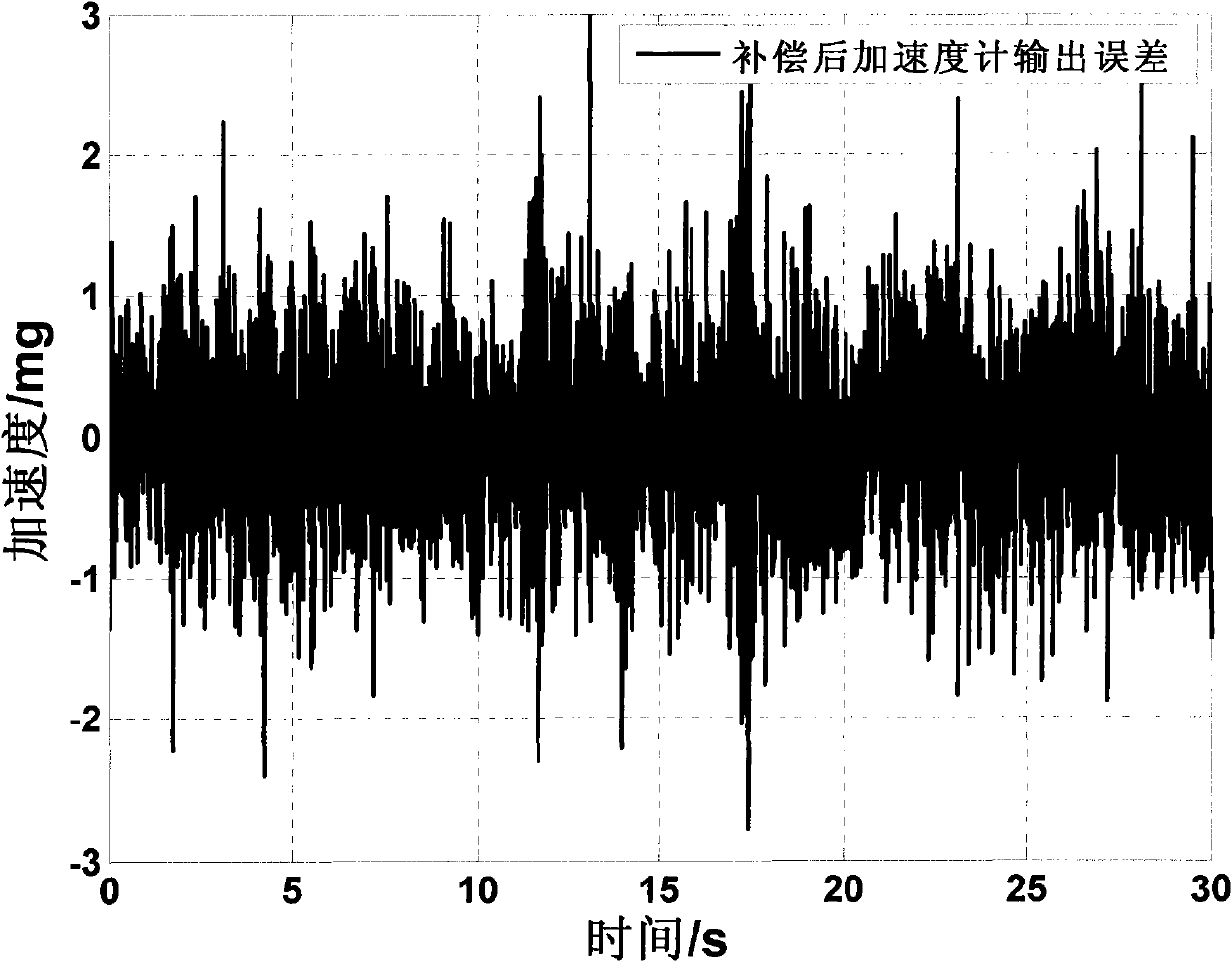
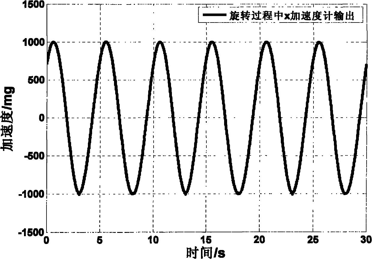
The invention relates to an accelerometer error calibration and compensation method based on a rotary mechanism, which comprises the following steps that: an accelerator is arranged on the rotary mechanism according to a certain requirements; the relationship between the dynamic continuous output of the accelerator and the rotating angle of the rotary mechanism is obtained through the rotation of the rotary mechanism; and a least square method is used for estimating and obtaining the bias, the scale factor, the non-linear error coefficient of the scale factor, the cross-coupling error coefficient and the like of the accelerator. The method uses the rotary mechanism to estimate all error coefficients of the accelerator, and is characterized by accuracy, high efficiency, easy operation, high universality and the like. After the method estimates the error coefficients and carries out corresponding error compensation, the output precision of the accelerator can be greatly improved. The method is also applicable to the calibration of a gyroscope, and can greatly improve the precision in measuring the speed of a top.
Description
technical field The invention relates to an accelerometer error calibration and compensation method, which can be applied to the error calibration and compensation of other inertial devices such as gyroscopes, and belongs to the fields of inertial device testing and inertial navigation. technical background The inertial navigation system has the characteristics of full autonomy, high concealment, high bandwidth, and continuous output. It has strategic significance in national defense and is one of the most important equipment in the fields of aviation, aerospace, and navigation. The performance of inertial devices (gyroscopes and accelerometers) is the most important factor affecting the accuracy of inertial navigation systems. 80% of inertial navigation system errors are caused by device errors. Therefore, improving the accuracy of inertial devices is the most important factor in the development of inertial technology. research content. There are often two ways to improve...
Claims
Login to View More Application Information
Patent Timeline
 IPC IPC(8): G01P21/02
Inventor徐烨烽杨国梁张仲毅李魁
OwnerBEIHANG UNIV