AI technical title is built by PatSnap AI team. It summarizes the technical point description of the patent document.
A technology of coupling connection and suspension core, which is applied in the field of optical fiber and can solve the problems that do not involve single-core fiber coupling and so on.
Inactive Publication Date: 2010-10-06
HARBIN ENG UNIV
View PDF2 Cites 21 Cited by
Summary
Abstract
Description
Claims
Application Information
AI Technical Summary
This helps you quickly interpret patents by identifying the three key elements:
Problems solved by technology
Method used
Benefits of technology
Problems solved by technology
However, none of these techniques involve the coupling of a single-core fiber to a suspended-core fiber with an air cavity.
Method used
Image
Click on the blue label to locate the original text in one second.
Reading with bidirectional positioning of images and text.
Examples
Embodiment ( 1
[0033] Include the following steps:
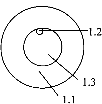
[0034] 1. If Figure 1-b For the suspended core optical fiber shown, peel off the coating layer at one end, and then clean it. During the cleaning process, prevent liquid from entering the hollow cavity of the suspended core optical fiber;
[0035] 2. Carefully cut out the flat suspension core fiber end face;
[0036] 3. Prepare the fiber end of the standard single-core fiber to be connected according to the same steps above;
[0037] 4. Put the prepared section of quartz protective tube on one end of standard single-core optical fiber or suspended core optical fiber;
[0038] 5. Butt and weld the prepared two optical fiber ends on the optical fiber welding machine, such as figure 2 As shown; the electrode high-voltage discharge causes the air cavity of the suspended core fiber after welding to collapse under the action of surface tension, and the cross-section of the solder joint forms a double-core solid fiber with two cores located i...
Embodiment ( 2
[0041] The second embodiment of the present invention is realized in the process of making and implementing, including the following steps:
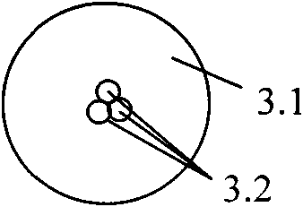
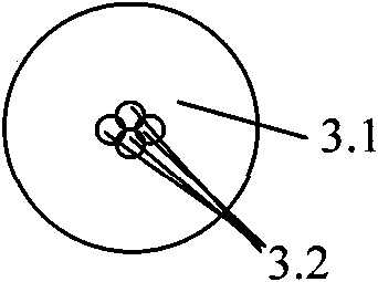
[0042] 1. Take as Figure 1-f For the suspended core optical fiber shown, peel off the coating layer at one end, and then clean it. During the cleaning process, prevent liquid from entering the hollow cavity of the suspended core optical fiber;
[0043] 2. Carefully cut out the flat suspension core fiber end face;
[0044] 3. Prepare the fiber end of the standard solid single-core fiber to be connected according to the same steps above;
[0045] 4. Put the prepared section of quartz protective tube on one end of standard single-core optical fiber or suspended core optical fiber;
[0046] 5. Butt and weld the prepared two optical fiber ends on the optical fiber welding machine, such as figure 2 As shown; the electrode high-voltage discharge causes the air cavity of the suspended core fiber after welding to collapse under the action of ...
PUM
Abstract
The invention provides a coupling method for suspended-core optical fibers. The coatings of the respective ends of a suspended-core optical fiber and a single-core optical fiber are stripped, the suspended-core optical fiber and the single-core optical fiber are washed and cut after stripping, so that the end surfaces of the optical fibers are smooth, an optical fiber welder is used for welding the stripped parts, the fusion points of the two sections of optical fibers are heated to carry out a fused biconical taper process, the optical power is monitored at the same time, the fused biconical taper process is stopped when the waist of the taper is thin enough so that the optical power-monitoring value reaches the predetermined coupling optical power, so that a tapered coupled section is formed, a quartz protective sleeve is sleeved on the tapered coupled section, and both ends of the quartz protective sleeve between the standard optical fiber and the suspended-core optical fiber are sealed. The invention has the advantages of simplicity, easy operation, low cost, stable optical performance, compact structure, high coupling optical power and on-line monitoring and convenient optical fiber integration and sensing application, and provides effective method and technique for directly embedded a suspended-core optical fiber device into a standard single-mode optical fiber communication link.
Description
technical field [0001] The invention relates to the field of optical fiber technology, in particular to a method for coupling and connecting suspended core optical fibers and standard single-mode optical fibers or multi-mode optical fibers. Background technique [0002] The main functions of optical connectors and optical couplers are to connect, synthesize, bifurcate, convert and attenuate optical signals or optical energy. Therefore, it is an indispensable and important device in optical fiber communication systems, optical fiber local area networks (including computer optical fiber networks, microwave optical fiber networks, optical fiber sensor networks, etc.) and various optical fiber sensor systems. [0003] Optical fiber connection technology refers to combining the end faces of two optical fibers together. The basic requirement for the connection is to maximize the coupling of light energy from the input fiber to the receiving fiber. In addition to requiring small ...
Claims
Application Information
Patent Timeline
Application Date:The date an application was filed.
Publication Date:The date a patent or application was officially published.
First Publication Date:The earliest publication date of a patent with the same application number.
Issue Date:Publication date of the patent grant document.
PCT Entry Date:The Entry date of PCT National Phase.
Estimated Expiry Date:The statutory expiry date of a patent right according to the Patent Law, and it is the longest term of protection that the patent right can achieve without the termination of the patent right due to other reasons(Term extension factor has been taken into account ).
Invalid Date:Actual expiry date is based on effective date or publication date of legal transaction data of invalid patent.

