Check patentability & draft patents in minutes with Patsnap Eureka AI!

Flow control device

A flow control device and flow technology, applied in the direction of flow control using electric devices, valve devices, valve operation/release devices, etc., can solve the problems of flow setting value changes, influences, and deterioration of control flow stability, etc., to achieve manufacturing The effect of low cost and small size

Active Publication Date: 2010-10-06
YAMATAKE HONEYWELL CO LTD
View PDF1 Cites 4 Cited by
  • Summary
  • Abstract
  • Description
  • Claims
  • Application Information

AI Technical Summary

Problems solved by technology

As a result, the change of the valve driving current of the flow control device 3 has an influence on the flow setting value of the flow control device 2.
As mentioned above, since the change of the valve driving current of the flow control device 2 also affects the flow control device 3, the flow control device 2 and the flow control device 3 interfere with each other, and the number of connected flow control devices depends on The more it increases, the worse the stability of the flow rate set value is due to complex mutual interference, and as a result, the stability of the control flow rate also deteriorates.

Method used


Image

  • Flow control device
  • Flow control device
  • Flow control device

Examples


Embodiment Construction

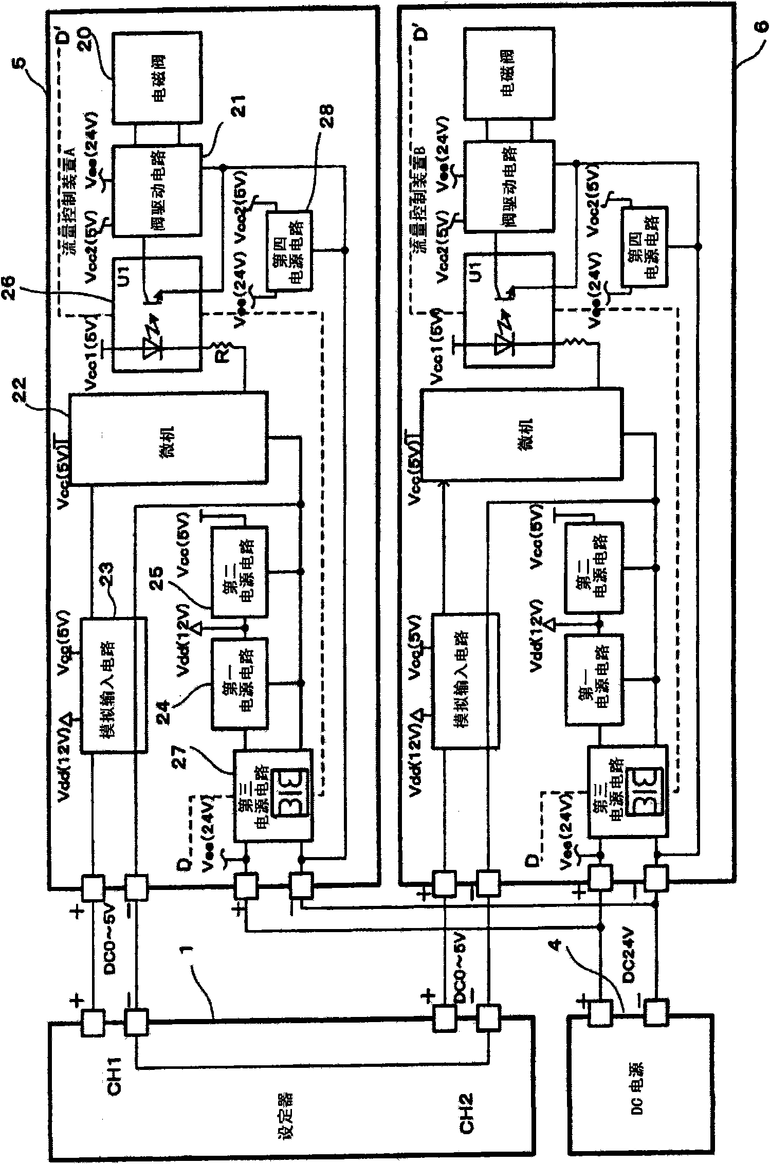
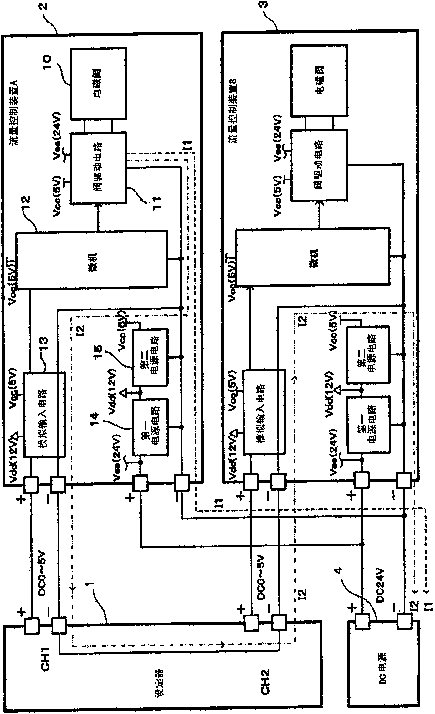
[0033] The flow control device of the present invention will be described in detail below based on the drawings. In the above "background art" and "technical problem to be solved", only the power supply circuit is insulated from other circuits. The structure of the flow control device of the present invention is such that the power supply circuit and the valve driving circuit are insulated from other circuits. figure 1 It is a structural diagram of the flow control device of the present invention, and the flow control devices 5 and 6 of the present invention are connected to the setter described in the above "background technology" and "technical problem to be solved".

[0034] The flow control devices 5 and 6 have a proportional solenoid valve 20 , a valve drive circuit 21 , a microcomputer (control unit) 22 , an analog input circuit 23 , a first power supply circuit 24 , and a second power supply circuit 25 . Furthermore, the flow control devices 5 and 6 further include a ...


PUM


Abstract

The invention provides a flow control device, and all flow control devices do not interfere with each other and can obtain accurate flow set by a setter. The flow control device receives an external power supply to operate, and is provided with a flow path through which fluid flows, a magnetic valve (20) for adjusting the aperture of the flow path, a valve driving circuit (21) for driving the magnetic valve, a flow measuring part for measuring the flow of the fluid flowing through the flow path and a control part which sends an indicating signal to the valve driving circuit so as to enable the flow and a set value to be consistent. The flow control device also is provided with an analog input circuit (23), a control part (22), a signal transmission part, an insulated power supply circuit and a non-insulated power supply circuit, wherein the analog input circuit is used for converting an analog voltage value or an analog current value input as a set value into a designated digital value or an analog value and transmitting the designated digital value or the analog value; the control part (22) is used for outputting the indicating signal according to the measured flow and the digital value or the analog value transmitted from the analog input circuit; the signal transmission part carries out electrically insulation on the control part (22) and the valve driving circuit, and transmits the indicating signal from the control part to the valve driving circuit; the insulated power supply circuit enables the analog input circuit, the control part and the valve driving circuit are electrically insulated, and provides power to the analog input circuit and the control part; and the non-insulated power supply circuit provides power to the valve driving circuit.

Description

technical field [0001] The invention relates to a low-cost and miniaturized flow control device which can eliminate the interference caused by the influence of the valve drive circuit, can correctly adjust the opening and closing of the valve to control the flow, and can realize low cost and miniaturization. Background technique [0002] Conventionally, as a flow control device, a device that is easily connected to a setting device for setting the flow rate from the outside (such as a digital device) has been developed. For example, there is known a flow control device that measures the flow rate of the fluid flowing through the flow path, and controls the regulating valve through a control means so that the flow rate of the fluid flowing through the flow path reaches a set flow rate. (For example, refer to Patent Document 1). [0003] Also, as the flow rate setting method of the flow control device, there are an input method of inputting a set value using an input key prov...

Claims


Application Information

Patent Timeline
IPC IPC(8): G05D7/06G01F1/26F16K31/06
Inventor 百濑修新井敏也
Owner YAMATAKE HONEYWELL CO LTD
Features
  • R&D
  • Intellectual Property
  • Life Sciences
  • Materials
  • Tech Scout
  • Unparalleled Data Quality
  • Higher Quality Content
  • 60% Fewer Hallucinations
Learn More