
Current balancing circuit and backlight module with same

A technology of current balance and backlight module, which is applied in the direction of electric lamp circuit layout, electric light source, electric light source, etc., can solve the problems of high manufacturing cost, large number of operational amplifier components, complex circuit, etc., and achieve high efficiency, simple circuit structure, Effect of reducing power loss

Inactive Publication Date: 2010-10-06
华映视讯(吴江)有限公司 +1
View PDF4 Cites 12 Cited by
  • Summary
  • Abstract
  • Description
  • Claims
  • Application Information

AI Technical Summary

Problems solved by technology

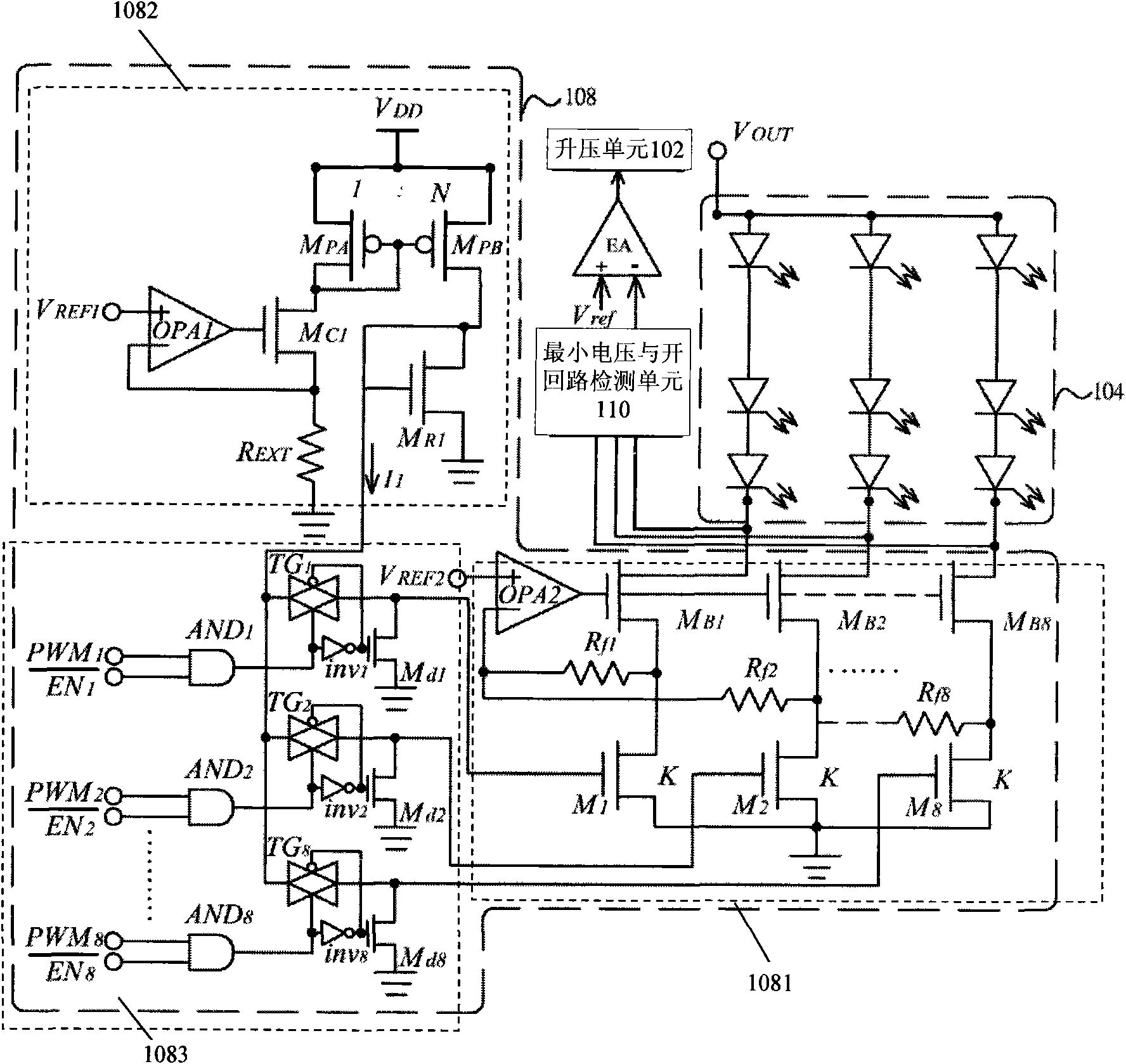
[0004] However, the devices or circuits disclosed in the above-mentioned known technologies are more complicated, require more operational amplifier components, and have higher manufacturing costs.

Method used


Image

  • Current balancing circuit and backlight module with same
  • Current balancing circuit and backlight module with same
  • Current balancing circuit and backlight module with same

Examples


Embodiment Construction

[0025] The present invention will be described in detail below in conjunction with its preferred embodiments and the accompanying drawings. It should be understood that the preferred embodiments in the present invention are only used for illustration rather than limiting the present invention. In addition, except for the preferred embodiment herein, the present invention can also be widely applied to other embodiments, and the present invention is not limited to any embodiment, but should be determined by the scope of the above claims.

[0026] Throughout this specification, "one embodiment" or "a embodiment" means describing a particular feature, structure, or characteristic of a preferred embodiment, and including at least one preferred embodiment of the present invention. Example. Therefore, the phrases "in one embodiment" or "in an embodiment" appearing in various places in this specification do not necessarily refer to the same embodiment. Furthermore, the particular fe...


PUM


Abstract

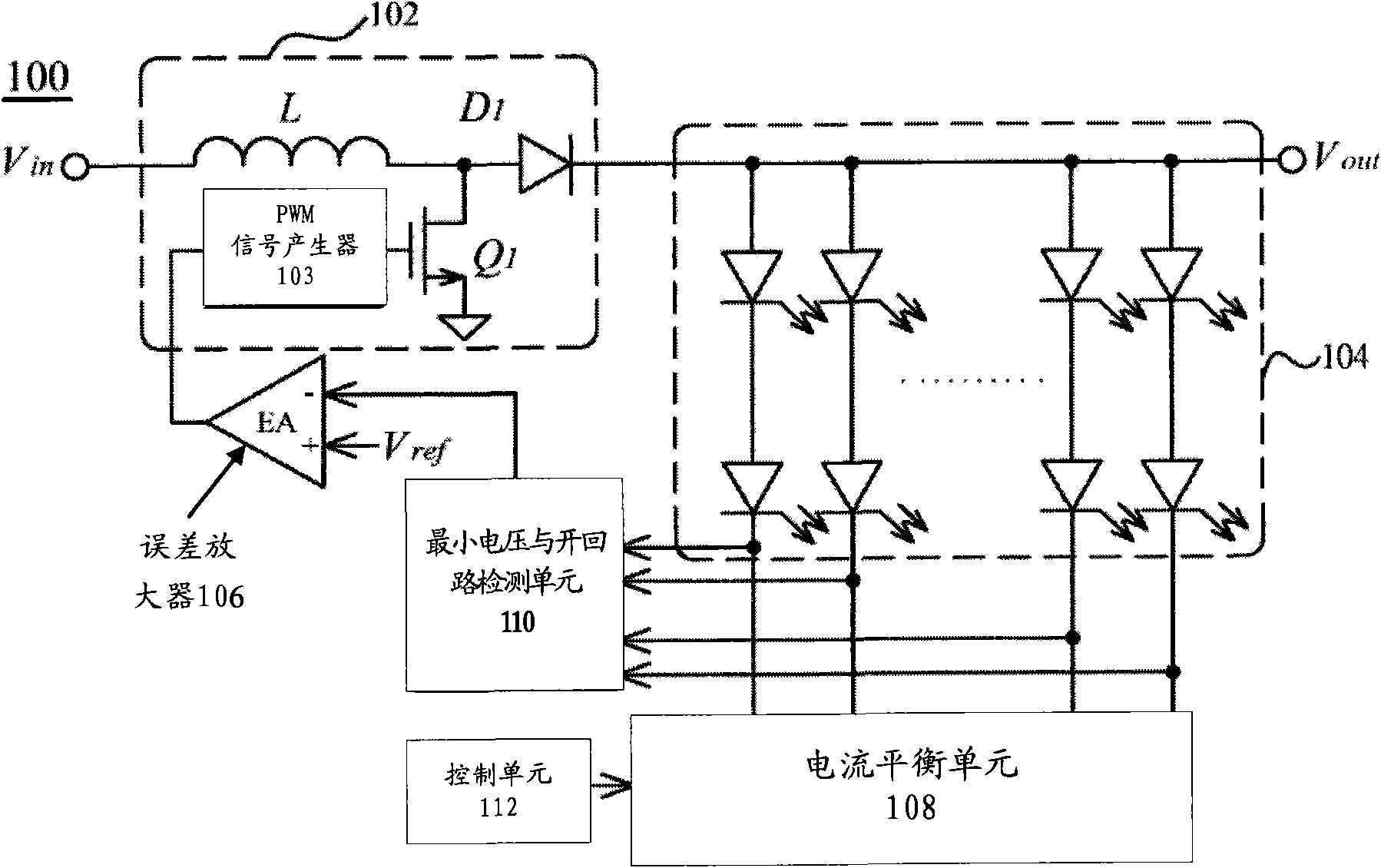
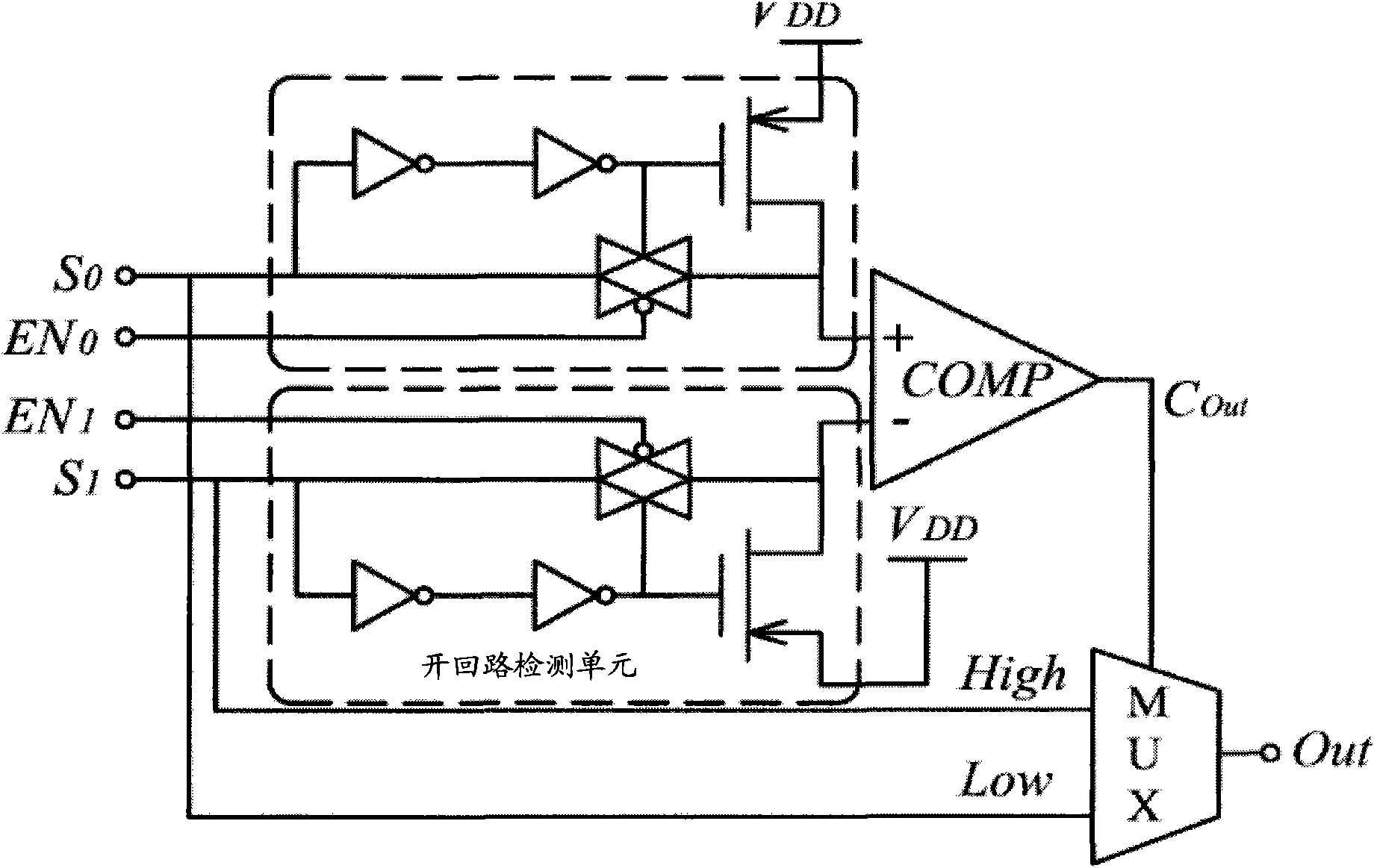
The invention relates to a current balancing circuit and a backlight module with the same. The current balancing circuit comprises a current balancing unit, a control unit and a detection unit, wherein the current balancing circuit is coupled to a plurality of light-emitting units so as to stabilize the current of the plurality of light-emitting units not be influenced by input voltage; the detection unit is coupled to the plurality of light-emitting units and the current balancing unit so as to be beneficial to detecting the minimum operation voltage of the light-emitting units; and the control unit is coupled to the current balancing unit so as to control the operation of the light-emitting units.

Description

technical field [0001] The invention relates to a circuit structure, in particular to a current balance circuit applied to a backlight source and a backlight module thereof. Background technique [0002] In the known driving methods of LEDs, the internal resistance and conduction voltage of the LEDs will be different due to differences in manufacturing processes or materials. The internal resistance of the light-emitting diode is easily affected by the manufacturing process or temperature, or the length and location of the circuit wiring coupled to this resistance, resulting in an error in the actual working equivalent resistance value and an error in the output drive current. The drive current of the one or multiple different loads coupled by one or multiple current mirrors will also cause errors. [0003] Please refer to US Patent Publication No. 2006 / 0082412, which discloses a channel-sharing operational amplifier method in the known technology. A multi-channel current ...

Claims


Application Information

Patent Timeline
Patent Type & Authority Applications(China)
IPC IPC(8): H05B37/02F21S8/00F21V23/00F21Y101/02
Inventor 陈科宏邱佳麟李菱刘家麟莫启能
Owner 华映视讯(吴江)有限公司
Learn More