A Wavefront Sensor Based on Adaptive Fitting

A wavefront sensor and wavefront sensing technology, which is applied in the direction of instruments, scientific instruments, optical radiation measurement, etc., can solve the problem of improving the Hartmann wavefront sensor, affecting the shape of the spot, the energy concentration of the spot, and the poor accuracy of the measurement results, etc. problem, achieve the effect of increasing measurement accuracy and realizing high-precision measurement

Active Publication Date: 2019-07-05
INST OF OPTICS & ELECTRONICS - CHINESE ACAD OF SCI
View PDF5 Cites 0 Cited by
  • Summary
  • Abstract
  • Description
  • Claims
  • Application Information

AI Technical Summary

Problems solved by technology

On the one hand, considering the higher the spatial sampling frequency of the measured wavefront by the microlens array, the better the approximation of the fitting slope to the measured wavefront, and the closer the reconstructed wavefront is to the measured wavefront, the measurement accuracy However, in practical applications, it is impossible to increase the measurement accuracy of the Hartmann wavefront sensor by increasing the number of microlens arrays without limit, and the measurement error of the Hartmann wavefront sensor increases with the On the other hand, considering the noise of the CCD (Charge-coupled Device, charge-coupled device) camera, background noise and pixel sampling error, the CCD camera will cause Centroid measurement error, and for the measured wavefront with large aberration, the aberration will seriously affect the shape of the spot and the concentration of the spot energy, resulting in inaccurate measurement of the spot centroid
[0005] The inventor found in the research that the Hartmann wavefront sensor in the prior art has poor measurement accuracy due to the existence of spatial sampling errors and centroid measurement errors

Method used


Image

  • A Wavefront Sensor Based on Adaptive Fitting
  • A Wavefront Sensor Based on Adaptive Fitting
  • A Wavefront Sensor Based on Adaptive Fitting

Examples


Embodiment Construction

[0044] The following will clearly and completely describe the technical solutions in the embodiments of the present invention with reference to the accompanying drawings in the embodiments of the present invention. Obviously, the described embodiments are only some, not all, embodiments of the present invention. The components of the embodiments of the invention generally described and illustrated in the figures herein may be arranged and designed in a variety of different configurations. Accordingly, the following detailed description of the embodiments of the invention provided in the accompanying drawings is not intended to limit the scope of the claimed invention, but merely represents selected embodiments of the invention. Based on the embodiments of the present invention, all other embodiments obtained by those skilled in the art without making creative efforts belong to the protection scope of the present invention.

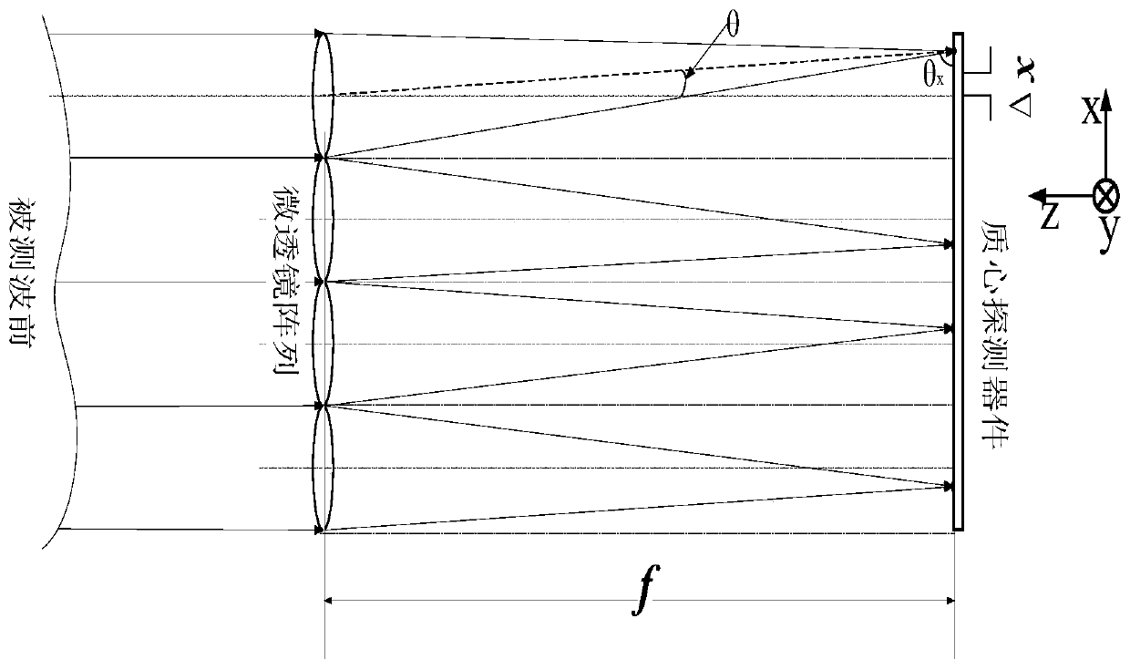
[0045] Considering the Hartmann wavefront sensor in ...


PUM


Abstract

The invention provides a wavefront sensor based on adaptive fitting. The wavefront sensor comprises a wavefront sensor, a wavefront fitting device and a wavefront recovery device. The wavefront sensor is used for receiving to-be-detected wavefront and carrying out segmentation and gathering processing on the to-be-detected wavefront so as to obtain a light spot array. The wavefront fitting device is used for carrying out recovery processing on the light spot array so as to obtain recovery wavefront and carrying out space iteration fitting processing on the recovery wavefront so as to obtain recovery wavefront compensation quantity reaching a stable value. The wavefront recovery device is used for carrying out recovery processing on the recovery wavefront compensation quantity which has reached the stable value so as to obtain recovery wavefront with high precision. The wavefront sensor carries out cycle measurement on error quantity subjected to compensation fitting under the effects of the wavefront fitting device, so when the cycle index is increased, error quantity fluctuations are reduced, the measurement precision is improved and high-precision measurement of the recovery wavefront is achieved.

Description

technical field [0001] The invention relates to the technical field of wavefront measurement, in particular to a wavefront sensor based on adaptive fitting. Background technique [0002] Wavefront measurement based on Hartmann wavefront detection technology has many advantages such as simple structure, convenient data processing, adjustable dynamic range, good real-time performance, etc., and has the characteristics of non-destructive and high precision, and has become a commonly used wavefront measurement. Devices are widely used in mirror surface shape detection, laser parameter diagnosis, flow field CT reconstruction, human eye aberration diagnosis, optical path collimation, etc. [0003] The Hartmann wavefront sensor in the prior art, as a wavefront testing instrument based on wavefront slope measurement, can divide the measured wavefront into several sampling units by the microlens array it includes, see figure 1 , these sampling units are collected at separate focal p...

Claims


Application Information

Patent Timeline
Patent Type & Authority Patents(China)
IPC IPC(8): G01J9/00
CPCG01J9/00G01J2009/002
Inventor 饶长辉马晓燠饶学军田雨鲍华
Owner INST OF OPTICS & ELECTRONICS - CHINESE ACAD OF SCI
Why Eureka
Try Eureka