Micromechanical rate-of-rotation sensor

一种转动率、微机械的技术,应用在转向感应设备、陀螺仪/转向感应设备、仪器等方向,能够解决不够稳健、冲击加速或振颤的影响易受干扰、粘附传感器不可用等问题,达到且稳健实施形式、紧凑实施形式的效果

Inactive Publication Date: 2010-10-06
MAXIM INTEGRATED PROD GMBH
View PDF2 Cites 26 Cited by
  • Summary
  • Abstract
  • Description
  • Claims
  • Application Information

AI Technical Summary

Problems solved by technology

[0007] Although in this way the rate of rotation can be detected as a function of the direction of the rate of rotation, the sensors known from the prior art are susceptible to disturbances due to their central suspension to the influence of external disturbance variables such as shock acceleration or vibrations, usually not robust
Strong relative positional changes between detection unit and substrate can thus occur, which in turn can lead to so-called sticking and unusable sensors

Method used


Image

  • Micromechanical rate-of-rotation sensor
  • Micromechanical rate-of-rotation sensor
  • Micromechanical rate-of-rotation sensor

Examples


Embodiment Construction

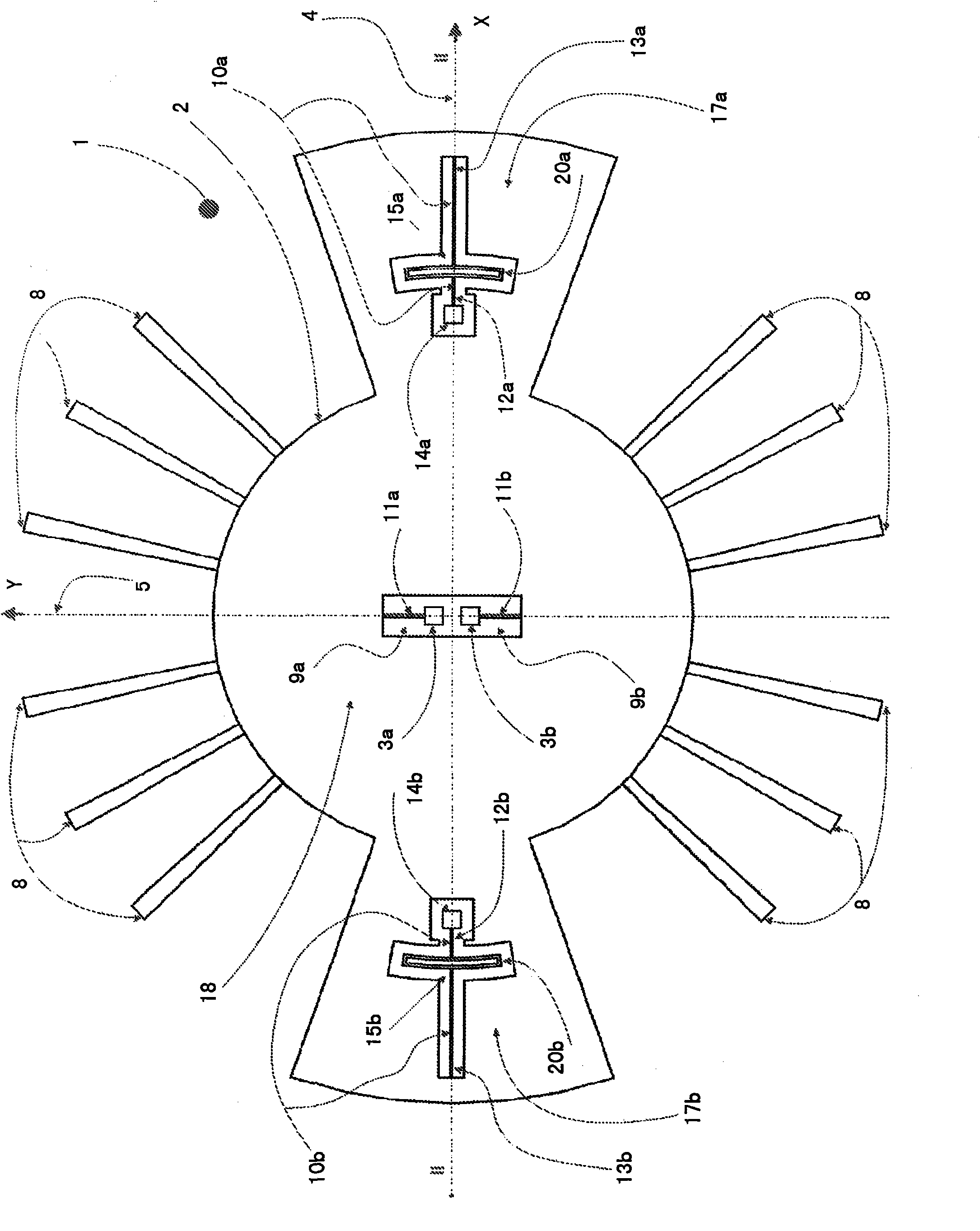
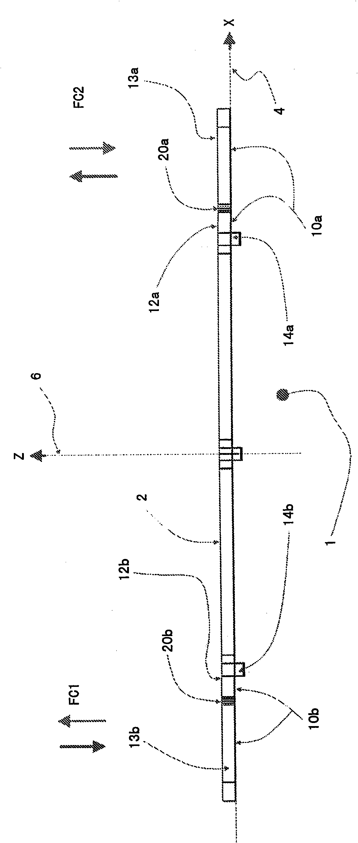
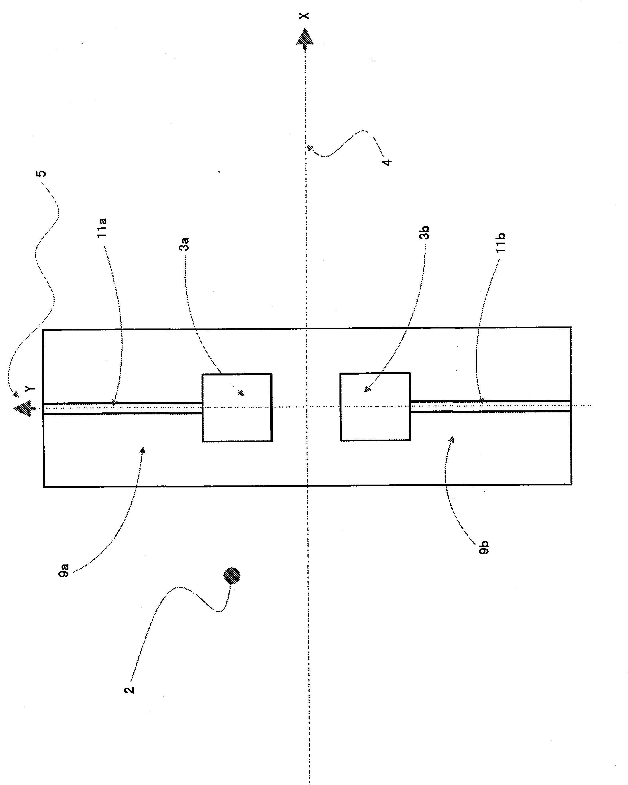
[0033] In the following description of the exemplary embodiment and in the figures, identical elements and functional units of the sensor are provided with the same reference numerals and designations. The Cartesian coordinate system shown in the drawings is the sensor reference system given in the general description of the invention. The Z axis of the Cartesian coordinate system ( figure 2 with Image 6 6) in figure 1 with Figure 5 extends vertically out of the drawing plane toward the viewer. Will figure 1 with figure 2 or Figure 5 with Image 6 Check together to get the exact position of the coordinate origin. In the following, the X-axis 4 is called the measurement axis 4 , the Y-axis 5 is called the detection axis 5 , and the Z-axis 6 is called the drive axis 6 .

[0034] In the first embodiment figure 1 The sensor shown in top view in FIG. 2 has a substrate 1 as a base element, which is sufficiently known from the prior art. A vibrating structure 2 is sup...


PUM


Abstract

The present invention relates to a micromechanical Coriolis rate-of-rotation sensor for detecting a rate of rotation about a measurement axis which is denoted the X axis below, having a substrate, an oscillation structure and means for generating a rotational oscillation about an excitation axis (Z axis) which is orthogonal to the measurement axis, wherein the oscillation structure is rotatably connected to the substrate by means of first, inner suspension means or by means of a central suspension means, with the result that it can carry out rotational oscillations about a fulcrum relative to the substrate, wherein at least one pair of second suspension means also connects the oscillation structure to the substrate and is arranged on opposite sides of the fulcrum, wherein the at least one pair of second suspension means is arranged at a greater radial distance from the fulcrum than the first, inner suspension means or the central suspension means in order to provide a micromechanical Coriolis rate-of-rotation sensor with a response behaviour which can be designed in a manner specific to the axis of rotation and with sufficient sensitivity to rates of rotation in one or more directions of rotation, which sensor simultaneously has sufficient robustness with respect to the effect of external shock or vibration in the measuring direction or directions (about a detection axis) in order to meet the requirements for electronic signal processing as far as possible and, in particular, to counteract the risk of the oscillation structure sticking on the substrate.

Description

technical field [0001] The invention relates to a micromechanical Coriolis rotational rate sensor for detecting the rotational rate about a measuring axis, referred to below as the X-axis. The micromechanical Coriolis rotational rate sensor has a substrate, a vibrating structure and means for generating rotational vibrations about an excitation axis (Z-axis) orthogonal to the measuring axis. The oscillating structure is rotatably connected to the substrate by means of an inner first suspension or by means of a central suspension, so that the oscillating structure can oscillate rotationally about a point of rotation relative to the substrate. Background technique [0002] Micromechanical rotational rate sensors are already known from the prior art, wherein a distinction can generally be made between decoupled sensors and coupled sensors. In the case of decoupled sensors, the vibrating structure has a drive element and a detection element which is mechanically separated from ...

Claims


Application Information

Patent Timeline
Patent Type & Authority Applications(China)
IPC IPC(8): G01C19/56
CPCG01C19/5712
Inventor H·哈默
Owner MAXIM INTEGRATED PROD GMBH
Why Eureka
Try Eureka